
Tire forming machine

A technology for tire building machines and building drums, which is applied in the field of tire building, and can solve problems such as transmission and positioning accuracy affecting tire building quality, weak adhesion of apex rubber bead rings, and poor composition ratio of capsule components, etc., to achieve novel structure, Improve the scope of application and design reasonable effects

Active Publication Date: 2016-08-03
EVE RUBBER RES INST +1
View PDF5 Cites 7 Cited by
  • Summary
  • Abstract
  • Description
  • Claims
  • Application Information

AI Technical Summary

Problems solved by technology

[0004] Second, an important step in the tire building process is the front-to-back wrapping process of the tire carcass material, especially in the turn-up process, most of the processes use capsules for turn-up, but because the capsules cannot be combined with the building drum in the past Rotate together, the carcass material and the capsule will be worn due to friction during the forming process, and the proportion of the composition and structure of the capsule is not good, resulting in greater wear and tear of the turned-up capsule in the tire turn-up process, which affects the control of production costs cause greater pressure
[0005] Thirdly, the apex rubber traveler should be buckled after wrapping and before turning it back. In the traditional buckle ring process, because the buckle structure is too simple, the apex rubber traveler is not bonded firmly, and it will also cause buckle The ring member is severely worn
[0006] Fourth, due to improper manufacturing process and improper material selection of the main shaft of the molding machine and the main shaft of the turn-up device, it is easy to cause premature wear and damage of the main shaft, which increases the production cost
At the same time, the transfer positioning accuracy of the carcass components also affects the quality of tire building

Method used

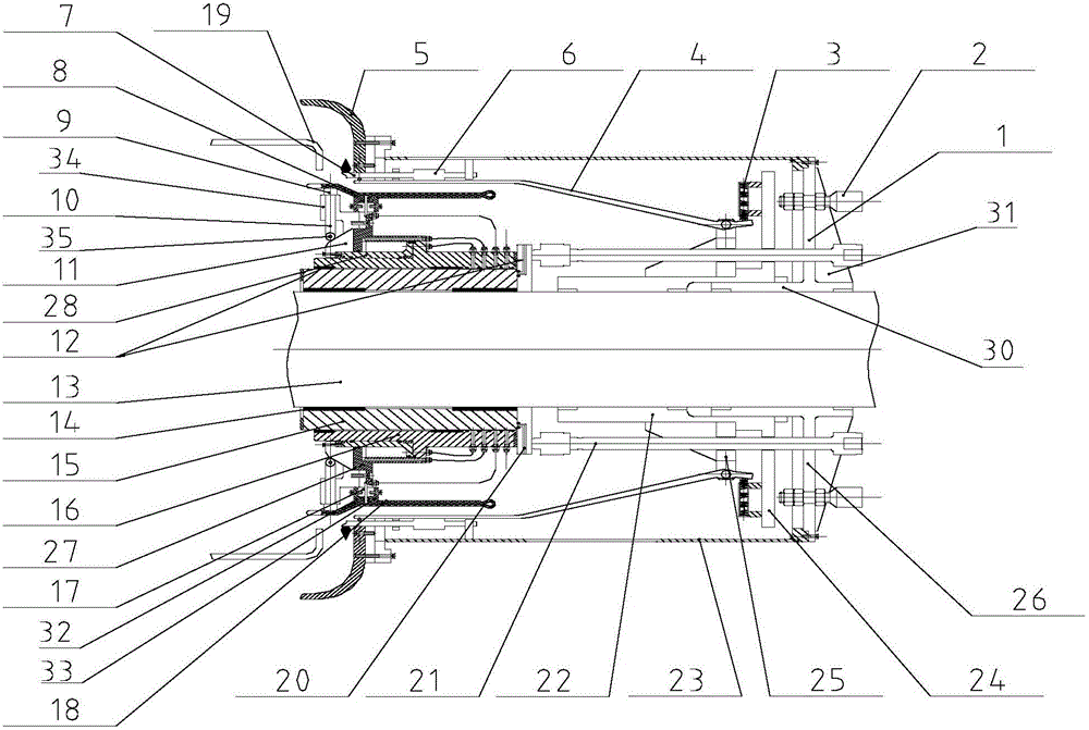

Image

  • Tire forming machine
  • Tire forming machine
  • Tire forming machine

Examples


Embodiment Construction

[0071] The present invention will be further described below in conjunction with the accompanying drawings.

[0072] 1. Tire building machine

[0073] 1. Overall structure

[0074] A tire building machine, comprising: a carcass drum 19, a belt drum and a building drum, and the building machine also includes:

[0075] The first carcass transfer device, which is located between the carcass drum 19 and the building drum, realizes the transmission of the first carcass assembly between the carcass drum 19 and the building drum; the first carcass transfer device can rotate, and it includes a reverse package device;

[0076] a second carcass transfer device, located between the building drum and the belt drum, enabling the transfer of the second carcass component between the building drum and the belt drum;

[0077] The belt drum, the second carcass transfer device, the building drum, the first carcass transfer device, and the carcass drum 19 are sequentially arranged on the same ...


PUM


Abstract

The invention discloses a tire forming machine which comprises a tire body drum, a belt layer drum and a forming drum. The tire forming machine further comprises a first tire body transmission device which is located between the tire body drum and the forming drum to achieve transmission of a first tire body assembly between the tire body drum and the forming drum, and a second tire body transmission device which is located between the forming drum and the belt layer drum to achieve transmission of a second tire body assembly between the forming drum and the belt layer drum. The first tire body transmission device can rotate. The belt layer drum, the second tire body transmission device, the forming drum, the first tire body transmission device and the tire body drum are sequentially arranged on the same axis.

Description

technical field [0001] The invention relates to a tire three-drum building device. It belongs to the field of tire molding. Background technique [0002] The tire molding process is not completed on one molding equipment, but different carcass components are made on different drums, and then all the carcass components formed in the previous process are transported to the last drum and manufactured out of the final product. In these processes, two-drum, three-drum, four-drum forming machines and their methods are usually used. The difference in manufacturing equipment determines the difference in the production process of the tire carcass. [0003] First, how to arrange each production device on the production line will directly determine the efficiency of production and the cost of the plant. [0004] Second, an important step in the tire building process is the front-to-back wrapping process of the tire carcass material, especially in the turn-up process, most of the pr...

Claims


Application Information

Patent Timeline
Patent Type & Authority Applications(China)
IPC IPC(8): B29D30/08
CPCB29D30/08B29D2030/086
Inventor 戴德盈卜庆勇孙兆田素霞秦丹
Owner EVE RUBBER RES INST
Learn More