
Cell fixture pushing device and automatic welding machine using the pushing device

A push device and cell clip technology, applied in auxiliary devices, welding equipment, auxiliary welding equipment, etc., can solve the problems of affecting the production efficiency of lithium batteries, the large volume of ultrasonic welding machines, and difficulty in ensuring moving accuracy, and simplify ultrasonic welding. process, optimize the production layout, improve the welding accuracy and the effect of

Active Publication Date: 2017-11-21
DONGGUAN HONBRO LI BATTERY EQUIP TECH
View PDF20 Cites 0 Cited by
  • Summary
  • Abstract
  • Description
  • Claims
  • Application Information

AI Technical Summary

Problems solved by technology

At present, the ultrasonic welding machine is mainly used for welding the cap and the positive ear. The ultrasonic welding machine mainly includes an ultrasonic generator, a pneumatic part, a transducer, a welding head and a welding seat. The welding is generally carried out by fixing the battery and moving the welding seat. , that is, the battery needs to be fixed in the corresponding fixture during welding, and at the same time, the welding seat is moved close to the cap of the battery, and the welding head of the welding seat moves to weld the cap and the positive tab. This welding method has many procedures and seriously affects the lithium battery. production efficiency, and it is necessary to set up corresponding equipment to move the ultrasonic welding machine, which increases the production cost of the enterprise. At the same time, due to the large size of the ultrasonic welding machine, it is difficult to ensure the movement accuracy, which affects the welding quality during welding

Method used


Image

  • Cell fixture pushing device and automatic welding machine using the pushing device
  • Cell fixture pushing device and automatic welding machine using the pushing device
  • Cell fixture pushing device and automatic welding machine using the pushing device

Examples


Embodiment Construction

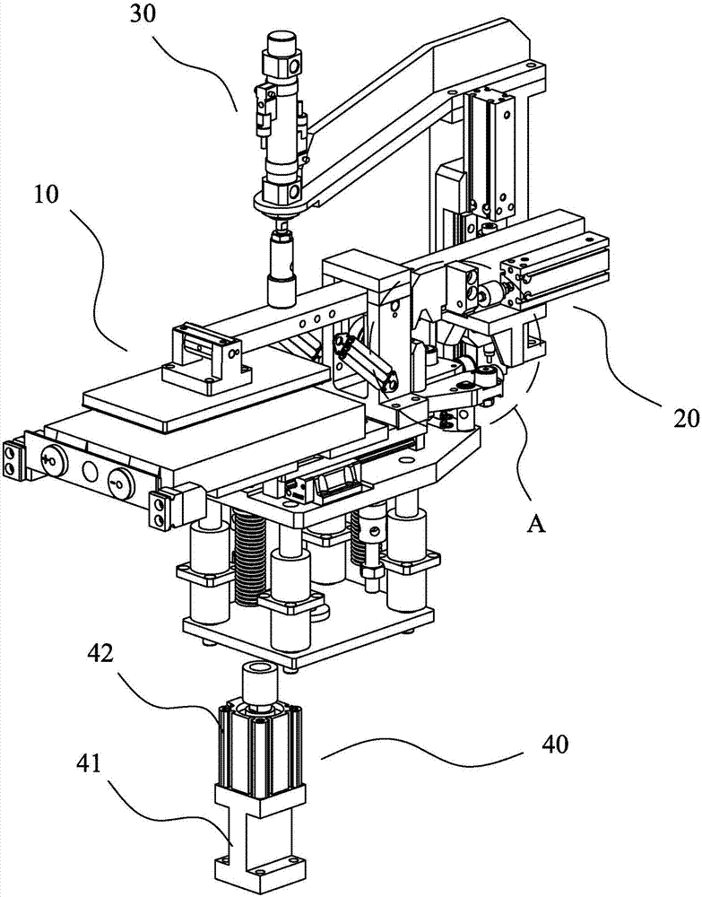
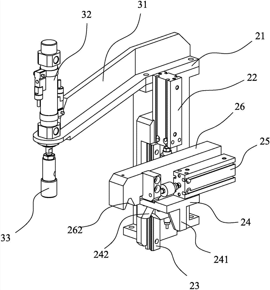
[0024] First, please refer to figure 1 As shown, a cell clamp pushing device includes a cell clamp 10, a pressing mechanism 30, a jacking mechanism 40 and a clamp pushing mechanism 20. The clamp pushing mechanism 20 is arranged behind the cell clamp 10 and is used to push The cells 50 on the cell fixture 10 are pushed forward; the pressing mechanism 30 is arranged above the cell fixture 10 for pushing the cells 50 on the cell fixture 10 downward; the lifting mechanism 40 It is arranged below the cell clamp 10 to hold the cell clamp 10 when the pressing mechanism 30 pushes the cell clamp 10 downward to prevent the position of the cell clamp 10 from shifting. The jacking mechanism 40 includes a telescopic rod. Push the cylinder 42 and the cylinder fixing seat 41 upward.

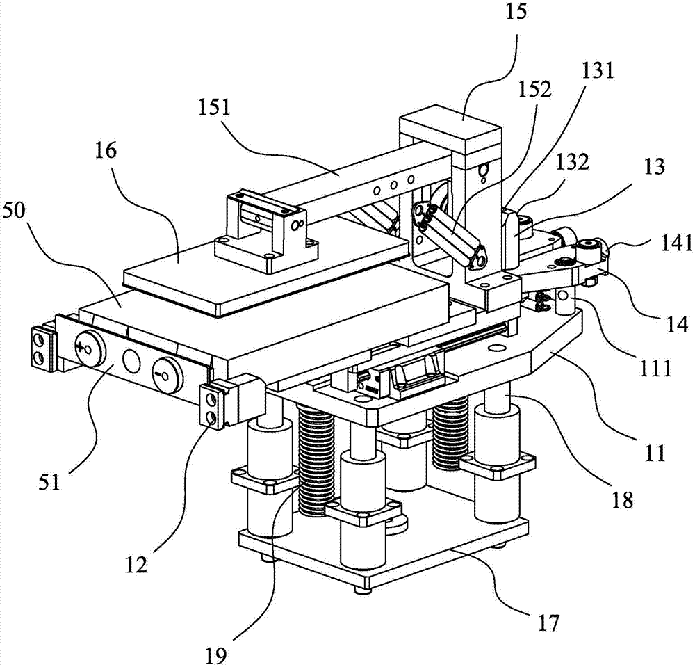
[0025] like figure 2 As shown, the cell fixture 10 includes a fixture bottom plate 17, a tray base 11, a cell pressure plate 16 and a cell tray 12. The tray base 11 is movably mounted on the fixture bottom p...


PUM


Abstract

The invention discloses a battery cell clamp pushing device which comprises a battery cell clamp and a clamp pushing mechanism. The clamp pushing mechanism comprises a pushing base, a pushing air cylinder and a pushing piece, wherein the pushing air cylinder and the pushing piece are arranged on the pushing base; and the pushing piece is movably arranged on the pushing base and can be driven by the pushing air cylinder to move. The battery cell clamp comprises a battery cell tray and a tray base, and the battery cell tray is arranged on the tray base and can be pushed by the pushing piece to move. By arranging the clamp pushing mechanism matched with the battery cell clamp, when ultrasonic welding is carried out on a battery cell, a welding base of an ultrasonic welding machine does not need to be moved any more, only the battery cell clamp needs to be pushed by the clamp pushing mechanism to the welding base, then welding of the battery cell can be achieved, the ultrasonic welding procedure is simplified, and the production efficiency of a battery is improved; and meanwhile, compared with a manner that the ultrasonic welding base is pushed to conduct welding, a manner of pushing the battery cell with small weight is higher in pushing accuracy, and the welding accuracy and the welding quality of the battery cell are improved.

Description

technical field [0001] The invention relates to the technology in the field of battery production, in particular to a battery cell fixture pushing device and an automatic welding machine using the pushing device. Background technique [0002] The lithium-ion battery is mainly composed of a shell, a cap, a positive electrode and a negative electrode. The positive electrode is welded to the cap through the positive electrode lug, and the negative electrode is welded to the bottom of the casing through the negative electrode lug. The cap is tightly placed at the opening of the casing. At present, when welding the cap and the positive lug, an ultrasonic welding machine is mainly used for welding. The ultrasonic welding machine mainly includes an ultrasonic generator, a pneumatic part, a transducer, a welding head and a welding seat. When welding, the battery is generally fixed and the welding seat is moved. , that is, the battery needs to be fixed in the corresponding fixture du...

Claims


Application Information

Patent Timeline
Patent Type & Authority Patents(China)
IPC IPC(8): B23K37/047B23K37/04
CPCB23K37/0443B23K37/047
Inventor 喻世民
Owner DONGGUAN HONBRO LI BATTERY EQUIP TECH
Learn More