
High-pass filter startup circuit

A technology of high-pass filter and start-up circuit, which is applied in the direction of frequency selection two-terminal pair network and multi-terminal pair network, etc. It can solve the problem that the high-pass filter cannot be started normally, and achieve the effect of solving the problem of not being able to start normally.

Active Publication Date: 2019-01-04
SHANGHAI BEILING
View PDF5 Cites 0 Cited by
  • Summary
  • Abstract
  • Description
  • Claims
  • Application Information

AI Technical Summary

Problems solved by technology

[0007] The starting circuit of the high-pass filter of the present invention can effectively solve the problem that the high-pass filter cannot be started normally

Method used


Image

  • High-pass filter startup circuit
  • High-pass filter startup circuit
  • High-pass filter startup circuit

Examples


Embodiment Construction

[0013] The start-up circuit of the high-pass filter of the present invention will be further described in detail below in conjunction with the drawings and specific embodiments, but it is not intended to limit the present invention.

[0014] refer to Figure 5 , is a structural schematic diagram of the start-up circuit of the high-pass filter of the present invention. A pair of diodes are respectively added to the input ends of the four operational amplifiers of the HPF. The cathode of the diode is connected to the input terminal of the op amp, and the other end is connected to the VCM level.

[0015] When the circuit enters a low-level stable state, the diode is turned on, and the input level of the operational amplifier is pulled up to VCM-VTH, where VTH is the conduction voltage of the diode, so that the operational amplifier starts and quickly enters the normal working state.

[0016] The above specific embodiments are only exemplary embodiments of the present invention,...


PUM


Abstract

The invention provides a high pass filter start circuit which is composed of a cascade of a number of operational amplifiers. Forward and reverse input ends of each operational amplifier are respectively connected with the cathodes of first and second diodes. The anodes of first and second diodes are connected with an auxiliary power supply together. The high pass filter start circuit provided by the invention can effectively solve the problem that a high pass filter cannot normally start.

Description

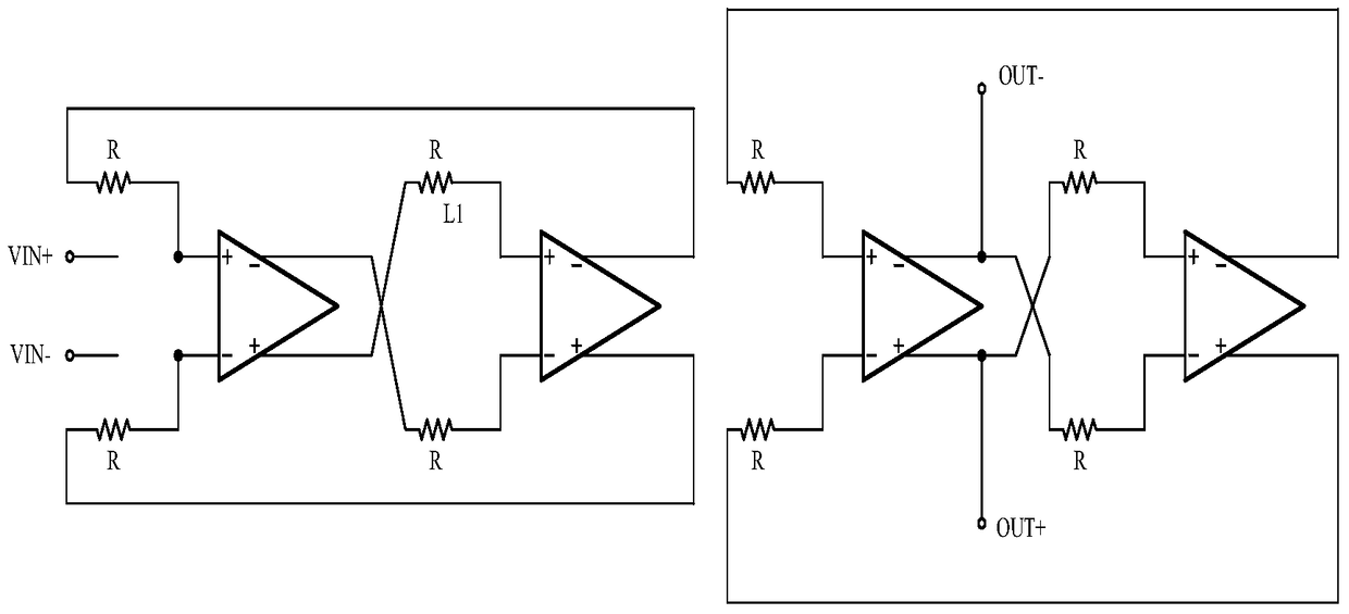
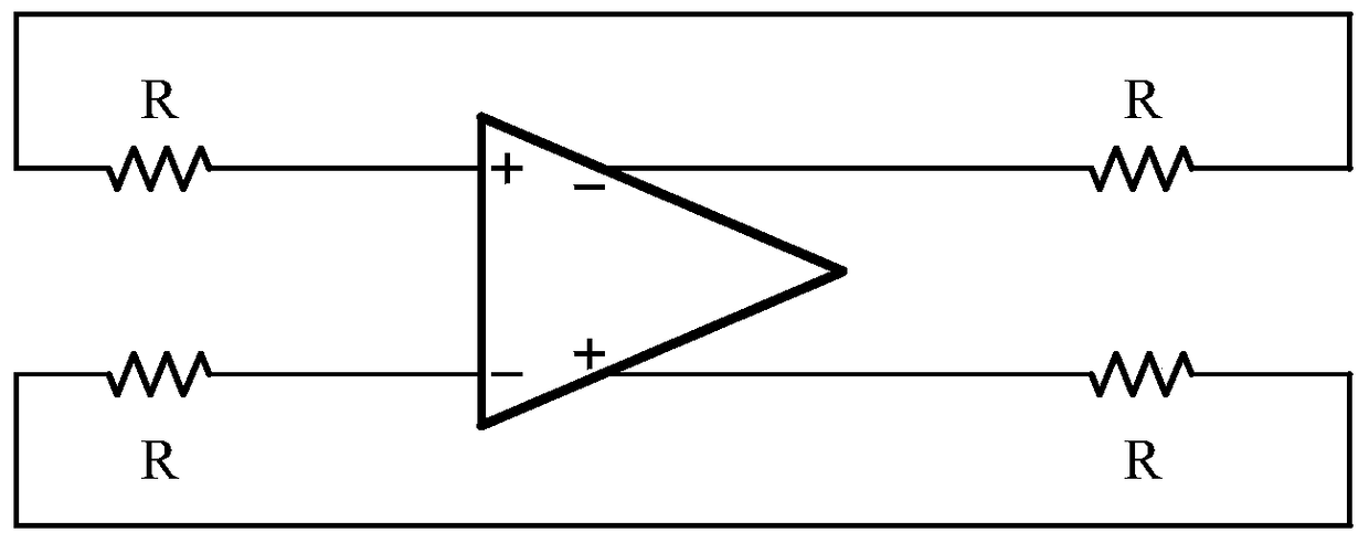
technical field [0001] The invention relates to a starting circuit of a high-pass filter. Background technique [0002] Generally, the HPF (high-pass filter) may fail to start during testing of general-purpose chips. When the HPF cannot be started, artificially add a large excitation signal to the input terminal of the chip, or artificially add a large excitation signal to the chip power supply, and the HPF can start to work normally. [0003] The circuit topology of HPF is as follows figure 1 As shown, if the figure 1 All the capacitive branches in are removed, and it can be obtained as figure 2 The DC topology circuit shown. figure 2 The 4 operational amplifiers are divided into two groups, and the two operational amplifiers in each group are connected end to end through resistors to form a closed-loop structure. This structure can be further simplified as image 3 , where the op-amp is structured as Figure 4 shown. [0004] According to the structure of the abov...

Claims


Application Information

Patent Timeline
Patent Type & Authority Patents(China)
IPC IPC(8): H03H11/04
Inventor 聂纪平阮颐
Owner SHANGHAI BEILING
Learn More