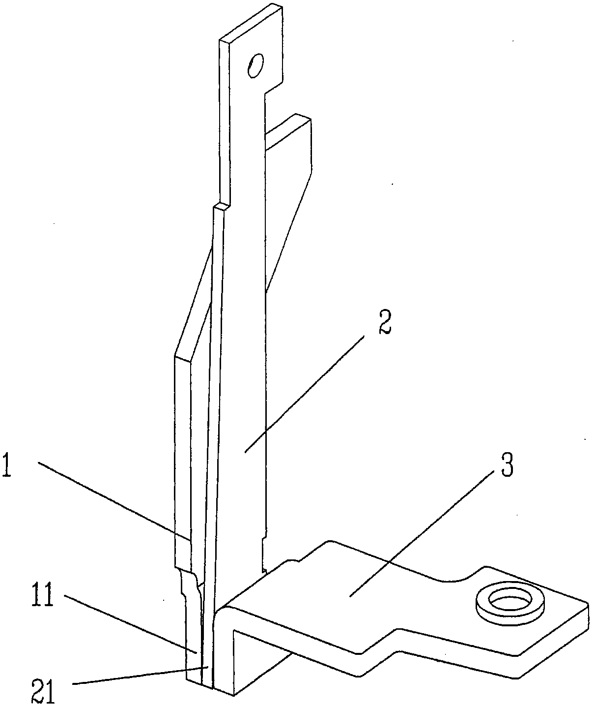
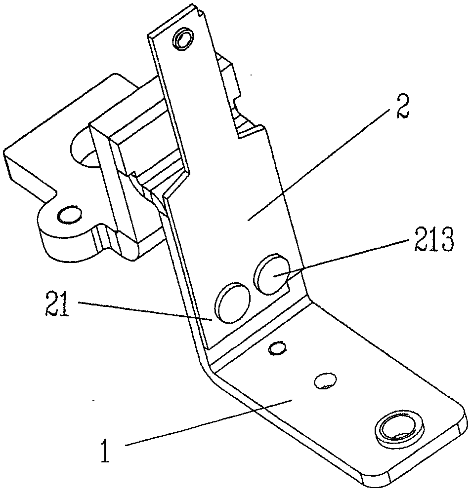
Thermal element structure of circuit breaker trip unit
A technology of thermal elements and circuit breakers, which is applied in the field of thermal element structures of circuit breaker releases, achieves good revisability, prevents waste of resources, and reflects economy.
- Summary
- Abstract
- Description
- Claims
- Application Information
AI Technical Summary
Problems solved by technology
Method used
Image
Examples
Embodiment 1
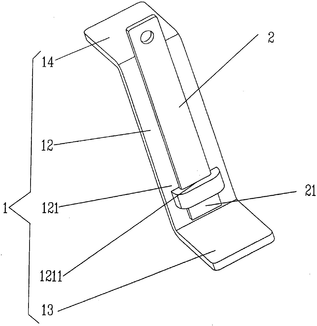
[0030] See image 3 , shows a heat element body 1 that generates heat when a current flows through it and a bimetal strip 2 (also called a bimetal element, the same below) for detecting heat. The geometric shape of the heat element body 1 is generally Z-shaped (also called "Zigzag"). Part, that is to say, the middle region in the height direction of the heating element body 1 constitutes the heating portion 12 of the heating element body. The root portion 21 of the aforementioned bimetallic strip 2 is connected to the root portion 121 of the heating portion 12 of the heating element body in a contacting manner.
[0031] As the technical points of the technical solution provided by the present invention: in this embodiment, the method of contacting the root 21 of the bimetal 2 of the aforementioned bimetal 2 with the root 121 of the heating part 121 of the heating part 12 of the aforementioned thermal element body In order to insert and connect the socket and the pin in the e...
Embodiment 2
[0036] See Figure 4 On the heating part root 121 of the heat generating part 12 of the heat element body and towards the side of the bimetal root 21, a half-enclosed pin cavity 1212 is formed, and the bimetal root 21 is mated with the half-enclosed pin cavity 1212. Depend on Figure 4 As shown, the shape of the pin cavity 1212 semi-enclosed is C-shaped, and is composed of two wings protruding from both sides of the heating part 12 of the heating element body and bending toward each other (by sheet metal working forming method). The rest are as described in Example 1.
Embodiment 3
[0038] See Figure 5 and Figure 6 On both sides of the bimetal root 21 of the aforementioned bimetal 2 and at positions corresponding to each other, a fixed seat insertion flange 211 is respectively extended, and a fixed seat is respectively provided at a position corresponding to the fixed seat insertion flange 211. Seat 4, the fixed seat 4 is positioned in the circuit breaker base of the circuit breaker in the use state, on the fixed seat 4 and at the position corresponding to the fixed seat inserting flange 211, there is an insertion groove 41, bimetallic The blade root 21 is fixed to the fixing seat 4 through the fixing seat inserting flange 211 in a state of being in contact with the heating part root 121 of the heating part 12 of the heating element body. The rest are as described in Example 1.
[0039] Depend on Figure 6 As shown, a distance is maintained between the aforementioned bimetal strip 2 and the heating portion 12 of the heating element body, and the gap ...
PUM
 Abstract
Description
Claims
Application Information
 - R&D
- Intellectual Property
- Life Sciences
- Materials
- Tech Scout
- Unparalleled Data Quality
- Higher Quality Content
- 60% Fewer Hallucinations
Browse by: Latest US Patents, China's latest patents, Technical Efficacy Thesaurus, Application Domain, Technology Topic, Popular Technical Reports.
© 2025 PatSnap. All rights reserved.Legal|Privacy policy|Modern Slavery Act Transparency Statement|Sitemap|About US| Contact US: help@patsnap.com


