
Closed switch blade switching type reversible switch for two-phase motor

A reversing switch, closed technology, applied in the field of two-phase motor closed knife switch reversing switch, can solve the problems of low safety, increased friction, poor electrical contact, etc., to improve electrical contact performance, reduce Small operational resistance and improved safety

Inactive Publication Date: 2016-07-27
尹全权
View PDF1 Cites 1 Cited by
  • Summary
  • Abstract
  • Description
  • Claims
  • Application Information

AI Technical Summary

Problems solved by technology

[0002] The reversing switch is a commonly used component in electromechanical equipment, mainly used for switching the reverse and forward rotation of the motor. The structure of the traditional reversing switch is relatively complicated, and the wiring is very confusing. For example, the Chinese patent: single-phase and three-phase motors are universally safe Shun switch, patent number: 201220123142.3 discloses a reversing switch, the wiring is very confusing, and it is very difficult for people who have a certain knowledge of electricity. The wiring of the two-phase double-capacitor motor is relatively simple. When rotating forward, the two terminals of the main winding coil of the motor are electrically connected to the two ends of the power supply line. Yes, but the wiring of the reversing switch of the above switch is very confusing, and it is very prone to wiring errors. The structure of the gate-opening switch is relatively simple compared with other structures, but the disadvantages are: 1. The connection shaft of the switch blade and the switch If the combination of the switch knife is too tight, the friction will increase, and it will be more laborious to move the switch. If it is too loose, it will easily cause poor electrical contact.
2. The charged body of the switching knife is outside the shell, which is less safe

Method used


Image

  • Closed switch blade switching type reversible switch for two-phase motor
  • Closed switch blade switching type reversible switch for two-phase motor
  • Closed switch blade switching type reversible switch for two-phase motor

Examples


Embodiment Construction

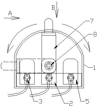
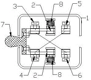
[0013] exist figure 1 , figure 2 , image 3 , Figure 4 In the middle of a closed arc-shaped shell 1, two middle contacts 2 are arranged horizontally, and the inverted contact A3 and the inverted contact B4 are horizontally arranged at the left end thereof, and the forward contact C5 and the forward contact are horizontally arranged at the right end thereof. D6. All the contacts are arranged horizontally in two rows and three columns. On the two middle contacts 2, a double-connected movable switch knife 7 that can be moved left and right by 180 degrees is movable. On the two middle contacts 2 and the double-connected movable switch knife A compression spring 8 is arranged horizontally on the movable connection shaft of 7, and the inverted contact A3 is electrically connected with the forward contact D6, and the inverted contact B4 is electrically connected with the forward contact C5.


PUM


Abstract

A two-phase motor closed-type knife switching reversing switch, characterized in that two middle contacts (2) are arranged horizontally in the middle of a closed arc-shaped casing (1), and reverse contacts are arranged horizontally on the left end Point A (3), inverted contact B (4), on its right end horizontally follow contact C (5), follow contact D (6), and all contacts are arranged horizontally in two rows and three columns respectively. On the point (2) there is a double movable switch knife (7) that can be moved left and right by 180 degrees, and a horizontal switch is installed on the movable connection shaft between the two middle contacts (2) and the double movable switch knife (7). Compress the spring (8), and electrically connect the inverted contact A (3) with the forward contact D (6), and electrically connect the inverted contact B (4) with the forward contact C (5). When in use, the two ends of the main coil are respectively connected to two reverse contacts or forward contacts, and the switch knife is switched left and right to realize reverse and forward switching of the two-phase double-capacitance motor.

Description

technical field [0001] The invention belongs to the electromechanical field, and in particular relates to a two-phase motor closed-type knife switching reversing switch with simple structure. Background technique [0002] The reversing switch is a commonly used component in electromechanical equipment, mainly used for switching the reverse and forward rotation of the motor. The structure of the traditional reversing switch is relatively complicated, and the wiring is very confusing. For example, the Chinese patent: single-phase and three-phase motors are universally safe Shun switch, patent number: 201220123142.3 discloses a reversing switch, the wiring is very confusing, and it is very difficult for people who have a certain knowledge of electricity. The wiring of the two-phase double-capacitor motor is relatively simple. When rotating forward, the two terminals of the main winding coil of the motor are electrically connected to the two ends of the power supply line. Yes, ...

Claims


Application Information

Patent Timeline
Patent Type & Authority Applications(China)
IPC IPC(8): H01H21/54H01H21/12
CPCH01H21/54H01H21/12
Inventor 尹全权雷晓英
Owner 尹全权
Learn More