
Solar cell and electroluminescent device general testing device

A technology for electroluminescent devices and solar cells, which is applied to individual semiconductor device testing, measuring devices, components of electrical measuring instruments, etc., can solve the problems of complicated operation and high equipment requirements, avoid damage, improve accuracy and repeatability It is beneficial to the effect of customized processing and mass production

Inactive Publication Date: 2016-07-27
NANJING TECH UNIV
View PDF10 Cites 8 Cited by
  • Summary
  • Abstract
  • Description
  • Claims
  • Application Information

AI Technical Summary

Problems solved by technology

[0004] The technical problem to be solved by the present invention is: in order to overcome the problems of high equipment requirements and cumbersome operation caused by using a large glove box to test environment-sensitive photoelectric devices in the prior art

Method used


Image

  • Solar cell and electroluminescent device general testing device
  • Solar cell and electroluminescent device general testing device
  • Solar cell and electroluminescent device general testing device

Examples


Embodiment Construction

[0020] The present invention will be further described in detail below in conjunction with the drawings.

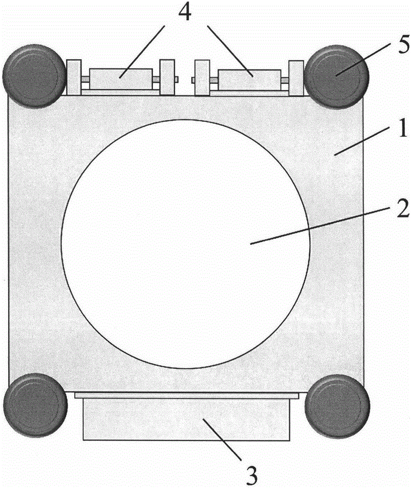
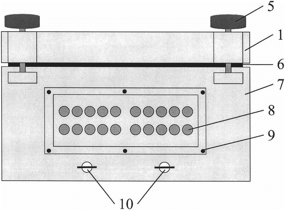
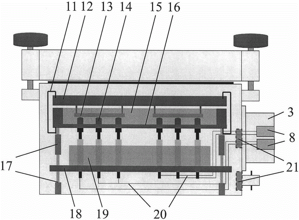
[0021] See Figure 1 to Figure 6 , Is a universal testing device for solar cells and electroluminescent devices according to an embodiment of the present invention. The device is used to test the optoelectronic performance and stability of several optoelectronic devices 13 at the same time. The test device includes: a test device housing top cover 1, an optically transparent window 2, a test device housing main body 7, a hinge 4 for connecting the housing top cover and the main body, a nut 5 for fixing the housing top cover and the main body, and a device The sealing ring 6 between the top cover of the housing and the main body, the electrode jack box 3, the electrode jack 8, the screw 9 for fixing the electrode jack box, the air inlet and outlet 10, the spring clip 11 for pressing the sample cover, the spring probe 14 , The sample table 15, the upper support platform 16, ...


PUM


Abstract

The invention relates to a photoelectric device testing device, in particular to a photoelectric performance testing device for solar cells and electroluminescent devices sensitive to air and humidity.The device comprises a testing device shell, an air inlet and outlet (for inert gas replacement), an optical transparent window, a sealing ring, a spring probe, an internal support platform, a sample table, a sample cover, a screw column, an electrode wire and an electrode jack.According to the testing device, after sample placement and gas replacement are completed in a glove box, the device can be removed from the glove box, and devices can be tested in the air atmosphere.Due to the pressure adjustable probe system of the testing device, damage caused by crocodile clips to device electrodes is avoided; the accuracy and stability of a testing result are improved; meanwhile, batch testing is promoted, and testing efficiency is improved.

Description

Technical field [0001] The invention relates to the technical field of optoelectronic devices, in particular to a photoelectric performance test device for solar cells and electroluminescent devices that are sensitive to air and humidity. Background technique [0002] In recent years, nano-optoelectronic devices represented by high-efficiency perovskite-type solar cells and organic light-emitting diodes have attracted widespread attention in academia and industry. Experts generally believe that nano-optoelectronic devices have extremely broad development space and industrial opportunities. After the fabrication of the optoelectronic device is completed, the performance of the prepared device needs to be tested, and then the device is subjected to efficiency calibration, yield evaluation, error analysis, parameter analysis and further optimization of technical parameters based on the test results. For a new generation of optoelectronic devices, such as perovskite solar cells, orga...

Claims


Application Information

Patent Timeline
Patent Type & Authority Applications(China)
IPC IPC(8): G01R31/26H02S50/10G01R1/067
CPCH02S50/10G01R1/06722G01R31/26Y02E10/50
Inventor 常进黄维
Owner NANJING TECH UNIV
Learn More