
A point-measuring mechanism of a led spectrometer and an led spectrometer

A spectrometer and LED lamp bead technology, which is applied in sorting, diode testing, single semiconductor device testing, etc., can solve problems such as poor contact of electrode pins, poor contact, large gaps, etc., to avoid the accumulation of residual glue and keep it in good condition The effect of contact

Active Publication Date: 2020-02-21
厦门多彩光电子科技有限公司
View PDF6 Cites 0 Cited by
  • Summary
  • Abstract
  • Description
  • Claims
  • Application Information

AI Technical Summary

Problems solved by technology

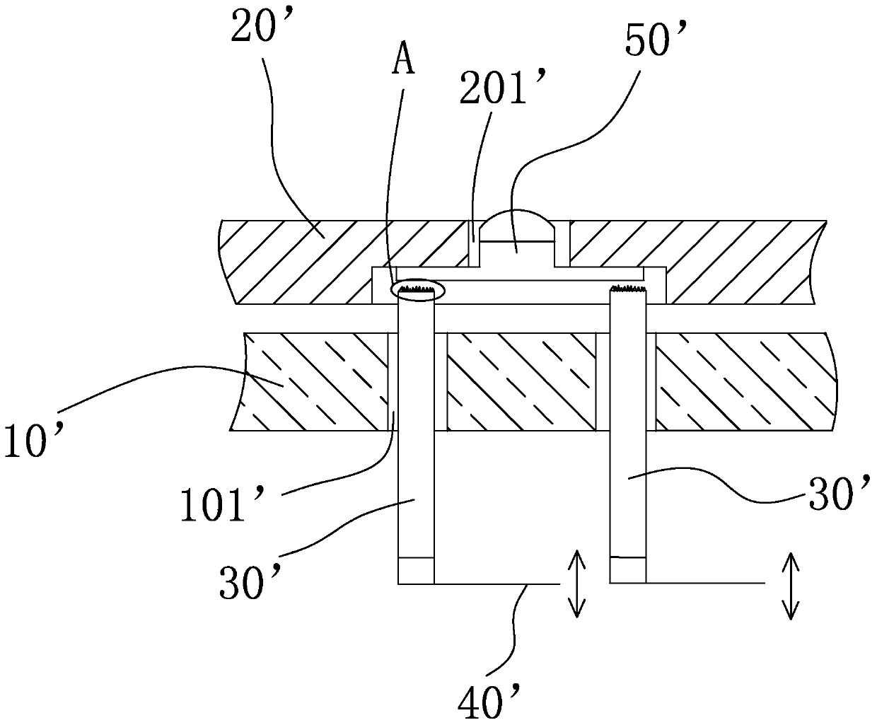
In the prior art, there are the following disadvantages: 1. The needle head of the probe 30' is designed in a jagged shape, which is easy to stick to the residual packaging glue of the LED lamp bead 50', causing the needle head to contact with the electrode pin of the LED lamp bead 50'. Poor contact will easily lead to inaccurate and failed tests; 2. There is a large gap between the probe 30' and the through hole 101' of the support plate 10'. The original intention of this design is to leave room for the probe 30' to move up and down
It is easy to cause the ideal contact with the electrode pin of the LED lamp bead 50'
The above-mentioned deficiencies will lead to poor contact of the LED lamp bead 50' during point measurement, resulting in no light or insufficient light, and the spectrometer will filter it out according to the test results of this time

Method used


Image

  • A point-measuring mechanism of a led spectrometer and an led spectrometer
  • A point-measuring mechanism of a led spectrometer and an led spectrometer
  • A point-measuring mechanism of a led spectrometer and an led spectrometer

Examples


Embodiment Construction

[0021] To further illustrate the various embodiments, the present invention is provided with accompanying drawings. These drawings are a part of the disclosure of the present invention, which are mainly used to illustrate the embodiments, and can be combined with related descriptions in the specification to explain the operating principles of the embodiments. With reference to these contents, those skilled in the art should understand other possible implementations and advantages of the present invention. Components in the figures are not drawn to scale, and similar component symbols are generally used to denote similar components.

[0022] The present invention will be further described in conjunction with the accompanying drawings and specific embodiments.

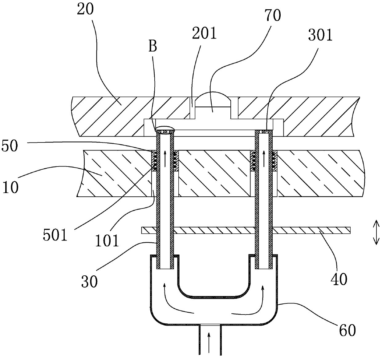
[0023] refer to figure 2 , image 3 As shown, a spot measuring mechanism of an LED spectrometer provided by the present invention includes: a support plate 10, a turntable 20, a power supply (not shown), a driving de...


PUM


Abstract

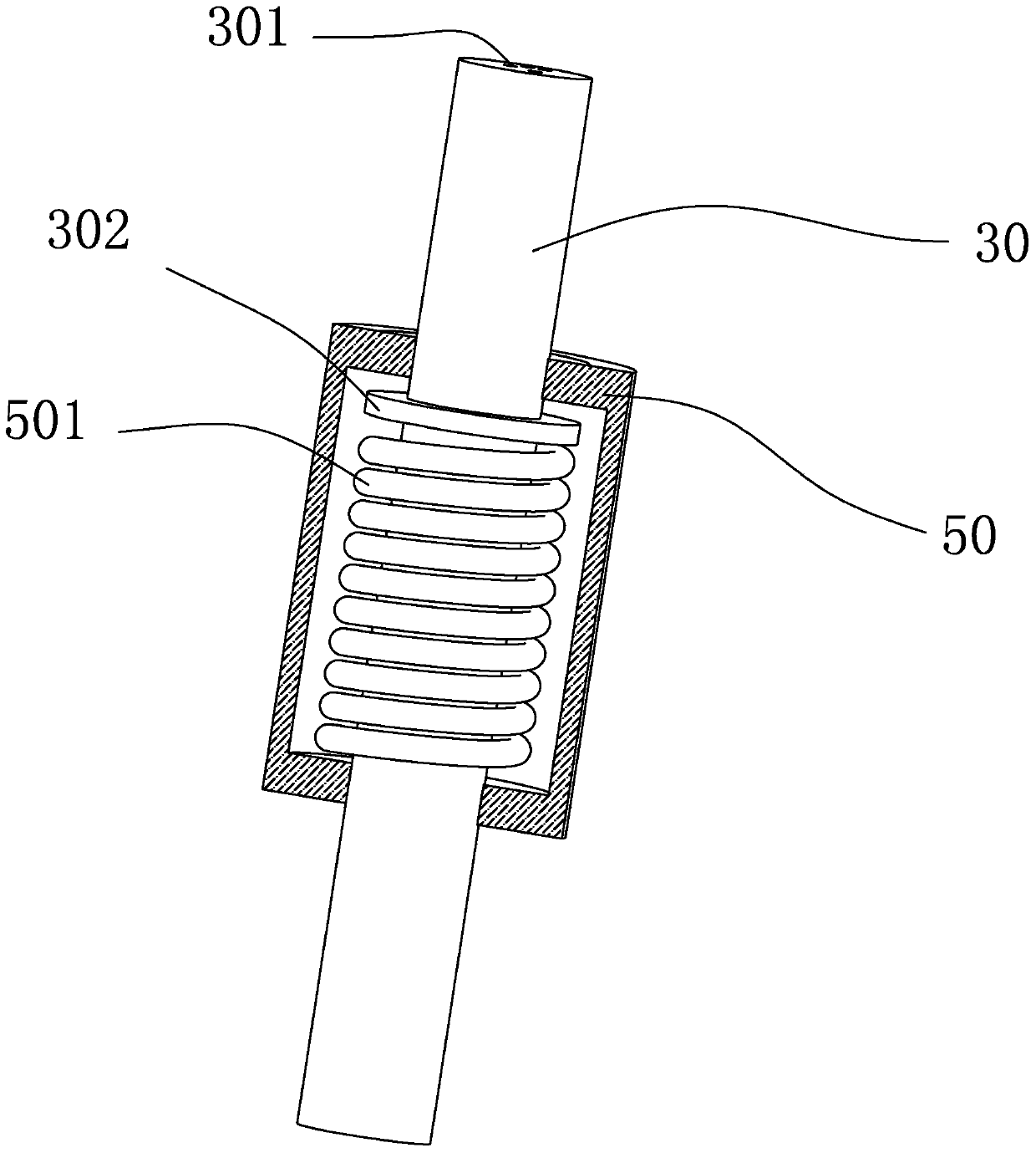
The invention relates to a spot measurement mechanism for an LED light sorting machine and the LED light sorting machine with the spot measurement mechanism, wherein the spot measurement mechanism is good in probe contact, long in service life, accurate in spot measurement testing and not prone to being stuck.According to the spot measurement mechanism for the LED light sorting machine, probes and an installation structure in the prior art are improved, each probe is provided with an air flow channel, the surface of a probe tip of each probe is provided with vent holes communicated with the corresponding air flow channel, air flow is blown off from the vent holes formed in the surfaces of the probe tips, residual packaging glue remaining on the testing probe tips can be cleaned away, and long-time good contact between the probe tips of the probes and electrode pins of LED lamp beads can be maintained; sleeves are additionally arranged, the sleeves are arranged on the probes in a sleeving mode and fixed in through holes, the probes can move relative to the corresponding sleeves, gaps between a support plate and the probes are filled with the sleeves, the residual packaging glue is prevented from entering the gaps, and contact point deviations caused by transverse displacement of the probes are avoided.The invention further provides the LED light sorting machine with the spot measurement mechanism.

Description

technical field [0001] The invention relates to a point measurement mechanism of an LED spectrometer with good probe contact, long service life, accurate point measurement and not easy to jam, and an LED spectrometer with the point measurement mechanism. Background technique [0002] LED (Light Emitting Diode), light-emitting diode, is a solid-state semiconductor device that can convert electrical energy into visible light, and it can directly convert electricity into light. Compared with ordinary lamps (incandescent lamps, etc.), the emergence of LED lamps has the advantages of energy saving, long life, good applicability, short response time, and environmental protection. [0003] After the LEDs are packaged into LED lamp beads, in order to determine the light effect, the light effect test is usually carried out on the spectrometer, and the LED lamp beads are screened according to the light effect, as disclosed in the Chinese utility model patent application number: 201520...

Claims


Application Information

Patent Timeline
Patent Type & Authority Patents(China)
IPC IPC(8): G01R31/26B07C5/342
CPCB07C5/342G01R31/2635
Inventor 高春瑞
Owner 厦门多彩光电子科技有限公司
Learn More