Hydraulic oil online monitoring device and engineering machinery

A monitoring device and hydraulic oil technology, which are used in the testing of fluid pressure actuation devices, mechanical equipment, and fluid pressure actuation systems, can solve the problems of low monitoring accuracy, high risk factor, and relatively large impact on monitoring equipment, and improve the safety effect

Active Publication Date: 2016-07-27
XCMG CONSTR MACHINERY
View PDF8 Cites 1 Cited by
  • Summary
  • Abstract
  • Description
  • Claims
  • Application Information

AI Technical Summary

Problems solved by technology

[0007] 1. High monitoring cost
Existing hydraulic oil on-line monitoring devices require special high-pressure resistant sensors, and the working conditions of related monitoring equipment are relatively harsh. The cost and technical requirements for monitoring equipment are relatively high, and it is easy to cause damage to monitoring equipment.
[0008] 2. High risk factor
The pressure and flow rate of the hydraulic system are relatively high. During the process of monitoring the hydraulic oil, it is very easy to cause failures such as system fuel injection, which may easily cause casualties and equipment damage.
[0009] 3. Low monitoring accuracy
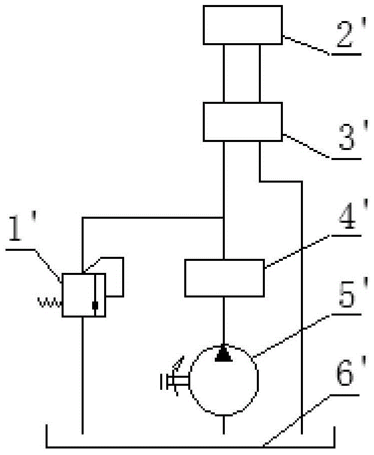
In the hydraulic oil online monitoring device of the high-pressure, high-flow rate hydraulic system, the monitoring module is installed between the outlet of the hydraulic oil pump and the main valve. The greater the pressure and flow rate, the more unstable the data monitored by the monitoring equipment, and the greater the deviation between the measured value and the offline test value; The viscosity, moisture, dielectric constant and other properties of the product are affected by the temperature far beyond the error range of the sensor itself; and in the high-pressure, high-velocity hydraulic system, the movement between the hydraulic oil molecules is violent, and the violent movement between the molecules has a great impact on the monitoring equipment. The use accuracy will cause different degrees of damage. The above reasons will cause the hydraulic oil monitoring accuracy to be relatively low.

Method used


Image

  • Hydraulic oil online monitoring device and engineering machinery
  • Hydraulic oil online monitoring device and engineering machinery
  • Hydraulic oil online monitoring device and engineering machinery

Examples


Embodiment Construction

[0042] The following will clearly and completely describe the technical solutions in the embodiments of the present invention with reference to the accompanying drawings in the embodiments of the present invention. Obviously, the described embodiments are only some, not all, embodiments of the present invention. The following description of at least one exemplary embodiment is merely illustrative in nature and in no way taken as limiting the invention, its application or uses. Based on the embodiments of the present invention, all other embodiments obtained by persons of ordinary skill in the art without creative efforts fall within the protection scope of the present invention.

[0043] The relative arrangements of components and steps, numerical expressions and numerical values ​​set forth in these embodiments do not limit the scope of the present invention unless specifically stated otherwise. At the same time, it should be understood that, for the convenience of descriptio...


PUM


Abstract

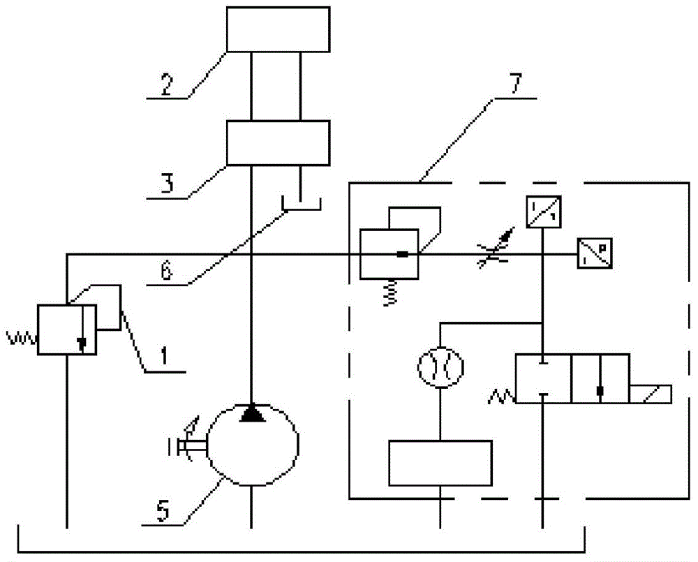
The invention discloses a hydraulic oil online monitoring device. The online monitoring device comprises a pressure and speed reduction unit and a monitoring module (4), wherein an inlet of the pressure and speed reduction unit is connected with a hydraulic system to be monitored, and an outlet of the pressure and speed reduction unit is connected with an inlet of the monitoring module (4). Due to the fact that the pressure and speed reduction unit is arranged and the monitoring module is arranged on the downstream side of the pressure and speed reduction unit, high-pressure and high-flow-rate hydraulic oil to be monitored is converted into low-pressure and low-flow-rate hydraulic oil on the premise that the normal use of the hydraulic system is not affected. Due to the reduction of the pressure and flow rate of the hydraulic oil to be monitored, the online monitoring safety of the hydraulic oil can be improved.

Description

technical field [0001] The invention relates to the field of construction machinery, in particular to a hydraulic oil online monitoring device and construction machinery. Background technique [0002] The hydraulic system is a system that can achieve a certain function by combining certain media through different hydraulic components. Hydraulic systems are widely used in construction machinery and production equipment. [0003] According to statistics, nearly 2 / 3 of the failures of the hydraulic system of construction machinery come from the pollution of the hydraulic oil medium. Most of the hydraulic systems of construction machinery are hydraulic systems with high pressure and high flow rate. In the existing technology, the technology for online monitoring of hydraulic oil in the construction machinery industry is still in a low pressure, low flow rate or static state. For dynamic hydraulic oil performance monitoring in The construction machinery industry is relatively s...

Claims


Application Information

Patent Timeline
Patent Type & Authority Applications(China)
IPC IPC(8): F15B19/00
Inventor 孙园园王月行潘燕
Owner XCMG CONSTR MACHINERY
Why Eureka
Try Eureka