
Automatic crimping device and press-fitting method for fusion-matching integrated tray of optical fiber distribution frame

A technology of optical fiber distribution frame and crimping device, which is applied in the direction of metal processing, metal processing equipment, manufacturing tools, etc., can solve problems such as time-consuming and labor-intensive, improper installation of adapters, and inaccurate control of the focus point, so as to avoid damage and reduce Effects on labor costs, increased productivity and assembly quality

Active Publication Date: 2017-12-29
CHANGZHOU TAIPING COMM SCI & TECH
View PDF6 Cites 0 Cited by
  • Summary
  • Abstract
  • Description
  • Claims
  • Application Information

AI Technical Summary

Problems solved by technology

[0003] In the assembly process of the existing fusion-matching integrated tray of the optical fiber distribution frame, the assembled adapter is placed in the adapter slot of the integrated fusion tray of the optical fiber distribution frame, and then the handle of the needle-nose pliers is held with the needle-nose pliers. The adapter is knocked on the front of the adapter, and the adapter is pressed into the adapter slot. However, there are the following defects in the press-fitting of the adapter by this method: 1. Because the handle of the needle-nose pliers is manually operated for press-fitting, the focus point It cannot be controlled accurately, and sometimes it will hit the plate, which may easily cause damage to the plate
2. Manual operation is not only time-consuming and labor-intensive, but also cannot guarantee the press-fit quality of the adapter, and there is still the phenomenon that the adapter is not installed in place
3. Because the adapter is pressed into the adapter slot by repeatedly hitting the adapter with needle-nose pliers, it is easy to damage the adapter and cause unnecessary waste

Method used


Image

  • Automatic crimping device and press-fitting method for fusion-matching integrated tray of optical fiber distribution frame
  • Automatic crimping device and press-fitting method for fusion-matching integrated tray of optical fiber distribution frame
  • Automatic crimping device and press-fitting method for fusion-matching integrated tray of optical fiber distribution frame

Examples


Embodiment Construction

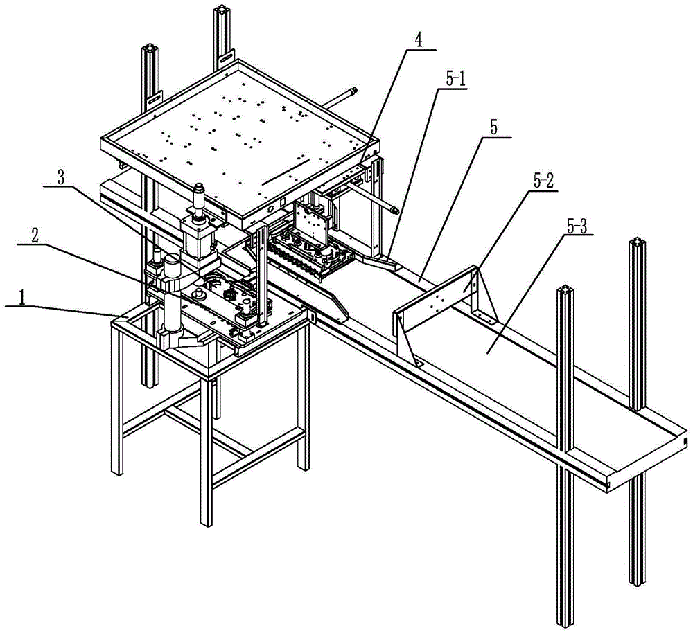
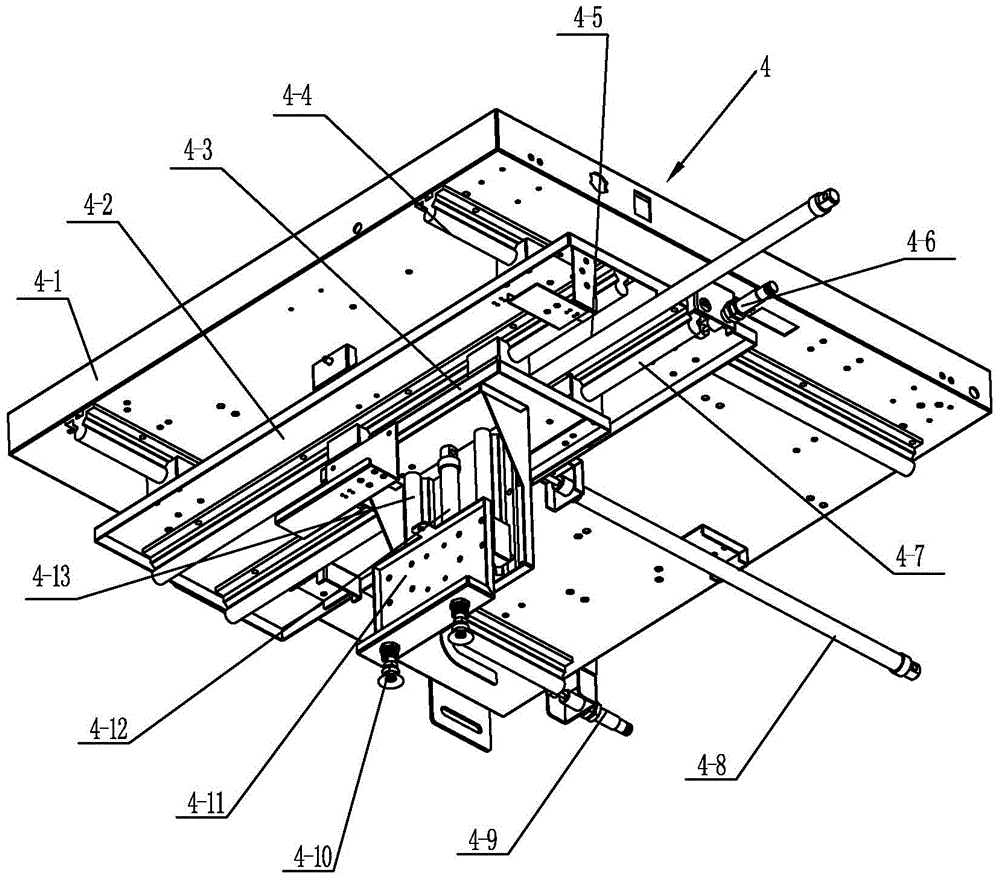
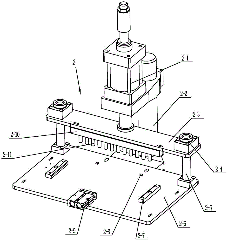
[0021] See figure 1 As shown, the automatic crimping device of the optical fiber distribution frame of the present invention includes a frame 1 , a feeding mechanism 4 , a crimping mechanism 2 and a conveying mechanism 5 . The conveying mechanism 5 of the present invention includes a conveying frame, a motor installed on the conveying frame, and a transmission mechanism. The conveying frame of the present invention can be connected to the frame 1, or set independently. The first position sensor of the integrated disk 3, the position sensor adopts a photoelectric sensor and a travel switch, etc., and the transmission mechanism includes a driving wheel, a driven wheel and a conveyor belt 5-3 installed on the conveyor frame, and the conveyor belt 5-3 is installed on the driving wheel. On the wheel and the driven wheel, the motor drives the driving wheel to drive the conveyor belt 5-3 to move forward. See figure 1 As shown, a guide plate 5-1 is installed on the conveying frame o...


PUM


Abstract

The invention relates to an automatic crimping device for an optical fiber distribution frame melting and matching integrated disc, including a frame, a feeding mechanism, a pressing mechanism and a conveying mechanism; a motor and a transmission mechanism are arranged on the conveying mechanism of the conveying mechanism, and the feeding mechanism On the frame and above the conveyor belt, the feeding mechanism includes a top plate, a horizontal moving plate, a vertical moving plate and a lifting plate. At least two vacuum suction cups are installed on the lower part of the lifting plate; the pressing mechanism is installed on the frame and located on the conveyor belt. outside, the pressing mechanism includes a support seat, a crimping cylinder and a die assembly, and the die assembly includes an upper die plate and a lower die base plate, and two transverse limit plates, a longitudinal limit block, and a The cylinder and the second position sensor are positioned longitudinally, the lower part of the upper template has pressure columns corresponding to each adapter, and the moving end of the crimping cylinder is connected with the upper template. The invention has the advantages of simple structure, automatic crimping of adapters, reduction of labor costs, and improvement of production efficiency and assembly quality.

Description

technical field [0001] The invention relates to an automatic crimping device and a crimping method for an optical fiber distribution frame fusion-matching integrated disc, belonging to the technical field of wireless communication. Background technique [0002] Optical fiber distribution frame fusion and distribution integrated tray is an optical distribution product used for optical cable introduction, fixing and protection, optical cable terminal and pigtail fusion in optical fiber distribution frame, optical cable transfer box and other products. It has the functions of optical cable fixing and protection, optical cable Termination function, line adjustment function, and optical fiber core and pigtail protection function. The integrated optical fiber fusion disk has flexible configuration, simple installation and application, easy maintenance, and convenient management. It is an indispensable equipment for optical fiber communication cable network terminals, or relay poin...

Claims


Application Information

Patent Timeline
Patent Type & Authority Patents(China)
IPC IPC(8): B23P19/027
Inventor 刘金扬任献忠石新根吴锦辉
Owner CHANGZHOU TAIPING COMM SCI & TECH
Learn More