
A force applying device for calibration

A technology of force applying device and fixing device, which is applied in the field of test calibration, can solve problems such as difficulty in maintaining the on-site environment, large error in force application, and high work intensity, etc., achieves easier operation of force application size and direction, avoids installation failure, and reads Accurate and reliable results

Active Publication Date: 2019-09-13
JIANGXI CHANGHE AVIATION IND
View PDF3 Cites 0 Cited by
  • Summary
  • Abstract
  • Description
  • Claims
  • Application Information

AI Technical Summary

Problems solved by technology

In the beginning, to apply a specific force to the blade, the original method of hanging sandbags with steel cables is used. This method has a large work intensity and a large force error, and the site environment is difficult to maintain and other factors.

Method used


Image

  • A force applying device for calibration
  • A force applying device for calibration

Examples


Embodiment Construction

[0019] The present invention will now be described more fully with reference to the accompanying drawings, in which exemplary embodiments of the invention are shown. This invention may, however, be embodied in many different forms and should not be construed as limited to the exemplary embodiments set forth herein. Rather, these embodiments are provided so that this disclosure will be thorough and complete, and will fully convey the scope of the invention to those skilled in the art.

[0020] For ease of description, spatially relative terms such as "upper," "lower," "left," and "right" may be used herein to describe the relationship of one element or feature relative to another element or feature shown in the figures. It will be understood that the spatial terms are intended to encompass different orientations of the device in use or operation in addition to the orientation depicted in the figures. For example, if the device in the figures is turned over, elements described ...


PUM


Abstract

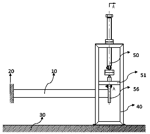
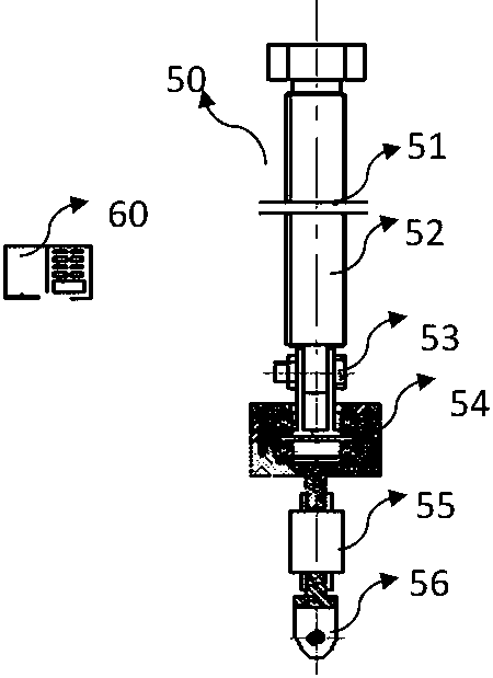
The invention provides a force applying device used for calibration, and is used for calibrating an experiment member. The force applying device comprises a threaded support, a rotating screw rod which is controlled to rotate by external force and rotates on the threaded support, a connecting bolt which is connected with the rotating screw rod, an anti-rotating mechanism which is connected on the rotating screw rod, a force sensor which is connected with the anti-rotating mechanism, and an adapter and a display device which are connected with the force sensor. The adapter is connected with the experiment member. The blades of a helicopter are calibrated by the force applying device so that calibration of the blades is enabled to be simple and easy to operate, clamping is stable and reliable, numerical reading is accurate and convenient and failure of installation of a member having service life can be avoided. The advantages of the force applying device are that the experiment member is accurate in installation and positioning, the force applying size and direction are easy to operate and numerical reading is accurate and reliable.

Description

technical field [0001] The invention belongs to the technical field of test calibration, in particular to a force applying device for calibration. Background technique [0002] According to the mandatory provisions of navigation mark HB5935 (article 6.2.3) and national military standard GJB720.4 (article 4.2.1), the blades of helicopters need to undergo design fatigue test and routine fatigue test. [0003] In order to realize the test, it is necessary to calibrate the test piece (blade) before the test, that is, apply a certain force to the strain, and obtain a set of force-strain correspondence through the transformation of the strain measurement mechanism. In order to apply a specific force to the blade at the beginning, the original method of using a steel cable to hang a sandbag, this method has a large work intensity and a large afterburning error, and the site environment is difficult to maintain and other factors. [0004] Therefore, it is necessary to design a forc...

Claims


Application Information

Patent Timeline
Patent Type & Authority Patents(China)
IPC IPC(8): G01M13/027
Inventor 梅火林赵越王斌应少军史丽红林娜
Owner JIANGXI CHANGHE AVIATION IND
Learn More