Permanent electromagnetic compounding semi-active vibration isolation actuator

An electromagnetic composite and semi-active technology, which is applied in the direction of shock absorbers, spring/shock absorber functional characteristics, magnetic springs, etc., can solve the problems that the system stiffness cannot be reduced, the system stiffness is increased, and the force transmission rate is large, so as to achieve good performance. Effects of vibration isolation, reduction of system stiffness, and reduction of complexity

Active Publication Date: 2016-07-20
HARBIN ENG UNIV
View PDF8 Cites 2 Cited by
  • Summary
  • Abstract
  • Description
  • Claims
  • Application Information

AI Technical Summary

Problems solved by technology

Electromagnetic actuators can only increase, not reduce, the stiffness of the system. The increase in stiffness can only be changed with the change of current, so the natural frequency of the system cannot be too small, which leads to the isolation of low-frequency vibrations limited to increasing the system Stiffness, so that the resonance peak moves to the high frequency band, thereby avoiding the resonance peak, but its force transmission rate is still relatively large, which affects the vibration isolation effect
Moreover, there are both passive vibration isolators and controllable stiffness actuators in the system, resulting in many components and complex structures

Method used


Image

  • Permanent electromagnetic compounding semi-active vibration isolation actuator
  • Permanent electromagnetic compounding semi-active vibration isolation actuator

Examples


Embodiment Construction

[0019] Hereinafter, the present invention will be described in more detail with examples in conjunction with the accompanying drawings:

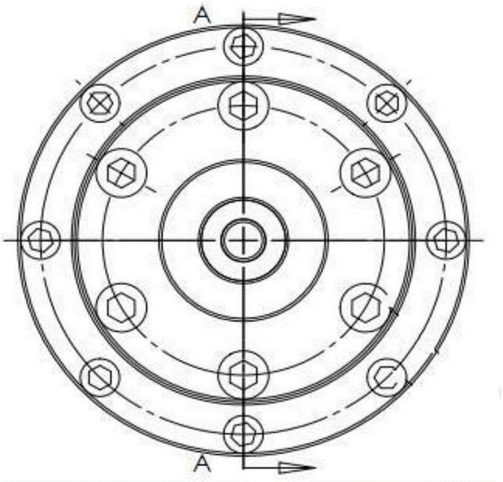
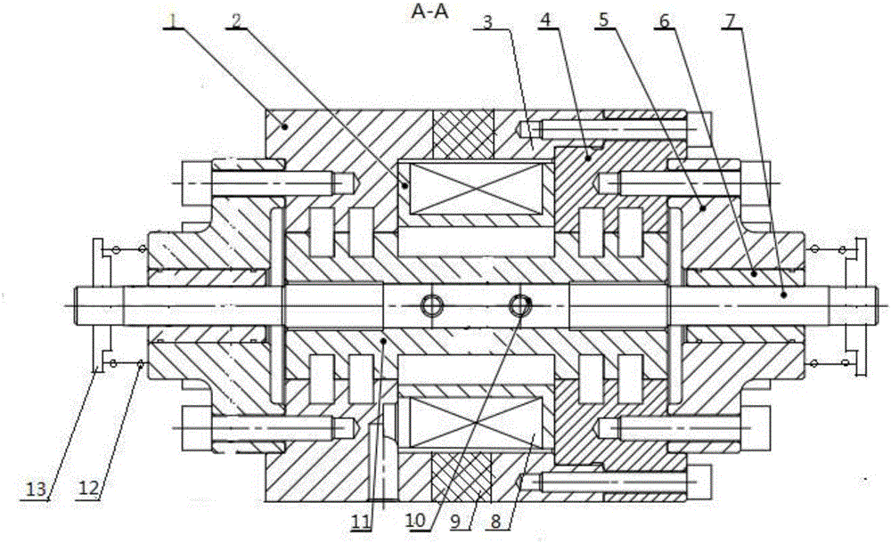
[0020] Combine Figure 1-2 , The present invention mainly includes the first housing 1, the coil former 2, the second housing 3, the flange 4, the bearing end cover 5, the linear bearing 6, the main shaft 7, the coil winding 8, the permanent magnet 9, the elastic cylindrical pin 10, Armature 11, spring 12, nut 13.

[0021] The first housing 1, the flange 4 and the armature 11 are provided with small teeth with variable pitch and tooth width, so that better linear characteristics of displacement-electromagnetic force can be obtained. A certain size of working air gap is left between the teeth on the first housing, the flanges and the teeth on the armature.

[0022] The first shell 1, the second shell 3, the flange 4 (ie the stator) and the armature 11 (ie the mover) are all made of electrical pure iron with good magnetic permeability; the permanen...


PUM


Abstract

The invention aims at providing a permanent electromagnetic compounding semi-active vibration isolation actuator. A permanent magnet is arranged between a first shell and a second shell. A hollow shell structure is jointly formed by the first shell, the permanent magnet and the second shell. A spindle is mounted in an armature, the armature is mounted in the shell structure, and the first end of the armature stretches out of the second shell. A flange and the end of the second shell are fixed. A first bearing end cover is fixed to the end of the first shell. A second bearing end cover is fixed to the end of the flange. The first bearing end cover and the second bearing end cover are arranged outside the two ends of the spindle correspondingly. The outer sides of the two ends of the spindle are each provided with a nut. Springs are mounted between one nut and the first bearing end cover and between the other nut and the second bearing end cover correspondingly. The permanent electromagnetic compounding semi-active vibration isolation actuator combines the functions of a passive vibration isolator and a controllable rigidity actuator in a traditional semi-active vibration isolation system, and meanwhile the problem that the passive vibration isolator in the traditional semi-active vibration isolation system is instable is solved.

Description

Technical field [0001] The invention relates to a vibration control device, specifically a vibration isolator. Background technique [0002] Mechanical vibration is almost everywhere in people's daily life, and its hazards are also well known. Vibration isolation (vibration isolation for short) technology is one of the most widely used technologies in the field of vibration control. It refers to the use of additional subsystems to isolate the vibration source from the object to be damped to reduce the impact of the vibration source on the vibration isolation object . Semi-active vibration isolation is a parameter control technology of the vibration isolation system. It adjusts the stiffness or damping of certain links in the vibration isolation system in real time according to the changes in system input and the requirements for system output, so that the system can obtain excellent power Academic characteristics. Compared with passive vibration isolation systems, semi-active ...

Claims


Application Information

Patent Timeline
IPC IPC(8): F16F6/00
CPCF16F6/00F16F2222/06F16F2228/06
Inventor 石勇宁一高孙军赵建辉郭强
Owner HARBIN ENG UNIV
Why Eureka
Try Eureka