
Fan drive

A transmission device and fan technology, applied in pump devices, machines/engines, mechanical equipment, etc., can solve problems such as difficulty in starting and affecting the life of the engine, achieve reasonable transmission structure, improve transmission ratio and transmission efficiency, and occupy less space. Effect

Inactive Publication Date: 2016-07-20
QINGDAO ALLITE AUTO TECHNIC
View PDF1 Cites 3 Cited by
  • Summary
  • Abstract
  • Description
  • Claims
  • Application Information

AI Technical Summary

Problems solved by technology

Difficulty starting and affecting engine life

Method used


Image

  • Fan drive

Examples


Embodiment Construction

[0019] Further illustrate the present invention below in conjunction with accompanying drawing.

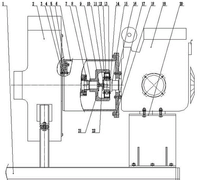
[0020] Such as figure 1 Shown, a kind of fan transmission device is characterized in that, comprises centrifugal fan 2, fan impeller shaft 7, clutch wheel 11, centrifugal clutch 13, small-sized diesel engine 19, described centrifugal fan 2, fan impeller shaft 7 and small-sized diesel engine 19 The output shaft of the engine is set coaxially, the centrifugal fan 2 is fixed on the underframe 1, and the outer side of the fan impeller shaft 7 is provided with a coupling seat 6, and the centrifugal fan 2 is connected with the bearing seat 5 by a hexagon head bolt I3, The bearing seat 5 is connected to the connecting seat 6, the left end of the connecting seat 6 is connected to the fan end cover 4 through the hexagonal head bolt I3, the right end of the connecting seat 6 is connected to the supporting seat flange 17 through the hexagonal head bolt IV18, and the supporting seat flange 17...


PUM


Abstract

The invention discloses a fan drive. A centrifugal fan, a fan impeller shaft and an engine output shaft of a small diesel engine are arranged coaxially, the centrifugal fan is fixed on an underframe, a connecting seat is arranged on the outer side of the fan impeller shaft, the centrifugal fan is connected with a bearing seat through hexagonal head bolts I, the bearing seat is connected with the connecting seat, the connecting seat is connected with a supporting seat flange through hexagonal head bolts IV, and the supporting seat flange is connected with the small diesel engine through hexagonal head bolts III; a clutch wheel is fixed on the fan impeller shaft through a flat key I; and a centrifugal clutch is fixed on a shaft sleeve of the output shaft of the small diesel engine through a flat key II. When the engine starts, the revolving speed of the output shaft is low, the clutch is not combined to the clutch wheel, and the engine can start in a no-load manner; and when the fan drive works, the engine is throttled up, the revolving speed is increased, the clutch is automatically combined to the clutch wheel, and transmission torque drives a fan impeller to rotate. The fan drive is reasonable in structure, stable in performance, relatively low in cost and convenient to operate.

Description

technical field [0001] The invention belongs to the technical field of transmission devices for vehicles, and in particular relates to a fan transmission device. Background technique [0002] As one of the sanitation equipment, the road sweeper is a new type of efficient cleaning equipment that integrates road cleaning, garbage recycling and transportation. The cleaning effect of the road sweeper depends largely on the selection of the fan. The larger the fan model, the greater the suction and the better the cleaning effect. The greater the air volume of the fan, the greater the power of the engine that needs to be selected. The existing road sweeper involves many parts and has a compact layout. The transmission device is usually positioned at the rear of the propulsion unit in the longitudinal direction and connected to one or more axles to drive the vehicle. [0003] A clutch device is designed in the transmission system in the prior art. For example, the patent name is ...

Claims


Application Information

Patent Timeline
Patent Type & Authority Applications(China)
IPC IPC(8): F04D25/08
Inventor 李金鸿赵新伟李洪宝
Owner QINGDAO ALLITE AUTO TECHNIC
Learn More