Plating device
A technology of plating solution and plating tank, applied in plating tank, cells, electrolytic components, etc., can solve the problems of unstable coating film quality and reduction of organic concentration.
- Summary
- Abstract
- Description
- Claims
- Application Information
AI Technical Summary
Problems solved by technology
Method used
Image
Examples
no. 1 approach
[0031] Hereinafter, a preferred embodiment for carrying out the present invention will be described. However, the technical idea of the present invention is not limited to the following embodiments.
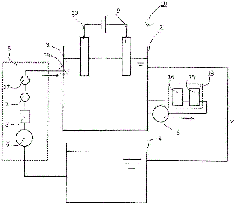
[0032] figure 1 A schematic diagram of the plating apparatus 20 of the first embodiment is shown in . The plating apparatus 20 of the present embodiment is equipped with: the plating tank 2 that is plated to the object 10 to be plated; The management tank 4 that stores the plating solution 3 overflowing from the plating tank 2; Plating solution conveying system 5 for circulating transport; anode electrode 9; impurity removal mechanism 19 connected with the plating layer to remove impurities from plating solution 3. The impurity removal mechanism 19 is divided into a carboxylic acid removal mechanism 15 and an alcohol removal mechanism 16 .
[0033] The plating solution 3 may contain conventionally known components used in electrolytic plating, and may contain metal ions of ...
no. 2 approach
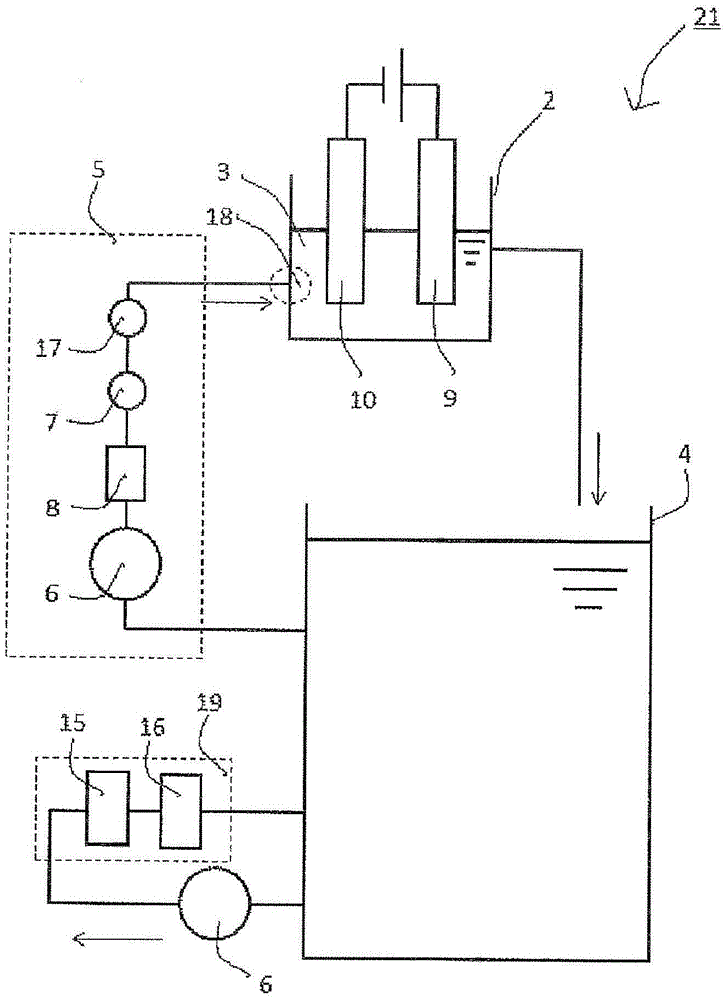
[0043] figure 2 It is a figure which shows the structure of the plating apparatus 21 in 2nd Embodiment. exist figure 2 Among them, the impurity removal mechanism 19 is connected to the management tank 4 . Other than that, it is the same as the plating apparatus 20 described in the first embodiment.
[0044] By connecting the impurity removal mechanism 19 to the management tank 4, the concentration change of the plating solution 3 in the plating tank 2 can be made more uniform. It has the effect of stabilizing the coating film thus obtained.
Embodiment
[0046] Hereinafter, the present invention will be further described with reference to examples and examples.
[0047] (Function confirmation of impurity removal mechanism)
[0048] The effect of the impurity removal mechanism in the copper sulfate plating solution will be described with reference to Examples 1 to 3. As a copper sulfate plating solution, 200 g / liter of copper sulfate pentahydrate, 100 g / liter of sulfuric acid, 50 mg / liter of hydrochloric acid, 100 mg / liter of polyethylene glycol (PEG) as an additive, bis(3-sulfopropyl) disulfide Prepare the plating solution with 8 mg / liter of SPS and 10 mg / liter of Yanlu Green B (JGB). A total of four substrates coated with a resist so as to have a thickness of 30 μm on a silicon wafer with a diameter of 6 inches were immersed in the above-mentioned copper sulfate plating solution, and left for 7 days to elute impurities to form a sample solution. It was confirmed that the carboxylic acid was acetic acid and the alcohol was 1...
PUM
 Abstract
Description
Claims
Application Information
 - Generate Ideas
- Intellectual Property
- Life Sciences
- Materials
- Tech Scout
- Unparalleled Data Quality
- Higher Quality Content
- 60% Fewer Hallucinations
Browse by: Latest US Patents, China's latest patents, Technical Efficacy Thesaurus, Application Domain, Technology Topic, Popular Technical Reports.
© 2025 PatSnap. All rights reserved.Legal|Privacy policy|Modern Slavery Act Transparency Statement|Sitemap|About US| Contact US: help@patsnap.com


