
Device for continuously preparing two-dimensional nano tin films

A two-dimensional nano-film technology, which is applied in the field of equipment for continuous preparation of two-dimensional nano-films, can solve the problems of poor electron transport performance, structural defects, and poor graphene film performance, and achieve large-scale production and application promotion. Effect

Inactive Publication Date: 2016-07-20
徐明生
View PDF3 Cites 2 Cited by
  • Summary
  • Abstract
  • Description
  • Claims
  • Application Information

AI Technical Summary

Problems solved by technology

However, the quartz tube furnace only has the functions of simple heat treatment of the metal catalyst layer and the synthesis of graphene film on the existing metal catalyst layer, and cannot realize the surface treatment of the substrate material and the preparation of synthetic graphene on the substrate. The continuous process of catalytic layer and graphene film synthesis; this kind of conventional high-temperature furnace has poor controllability to the required gas when synthesizing two-dimensional nano-films
Moreover, the graphene film synthesized by a quartz tube furnace has structural defects, resulting in poor electron transport performance. The quartz tube furnace has severely restricted the application of two-dimensional nano-films such as graphene films.
At the same time, roll-to-roll (roll-to-roll) equipment is currently used to prepare graphene films, but due to the limitations of this equipment technology and the requirements of the two-dimensional nano-film preparation technology, roll-to-roll equipment technology preparation The performance of the graphene film is still poor[ Carbon 50, 2615 (2012)]

Method used


Image

  • Device for continuously preparing two-dimensional nano tin films
  • Device for continuously preparing two-dimensional nano tin films
  • Device for continuously preparing two-dimensional nano tin films

Examples


Embodiment 1

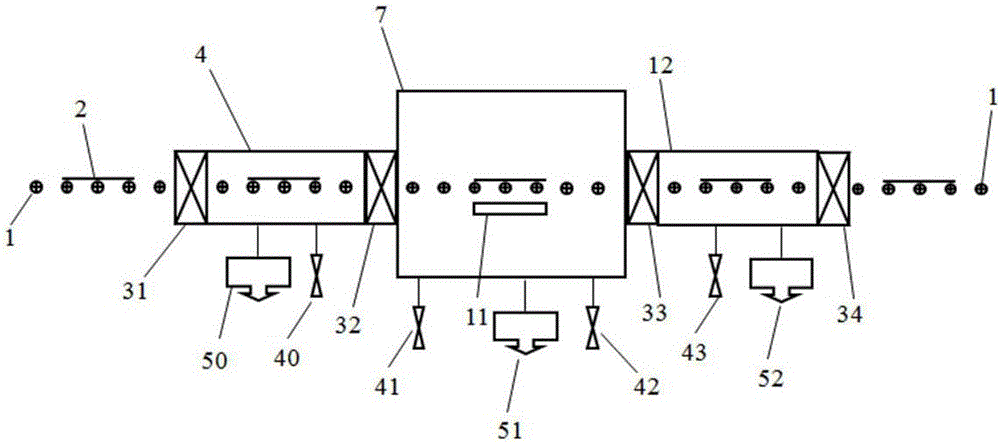
[0050] see figure 1 , the equipment for continuously preparing two-dimensional nano-films of the present invention comprises: a feed chamber 4, a sample preparation chamber 7, and a discharge chamber 12; The chambers 12 are all equipped with rollers 1 for transferring samples; the feeding chamber 4 is provided with a valve 31 connected to the atmosphere, and a valve 32 is arranged between the feeding chamber 4 and the sample preparation chamber 7, and the sample preparation chamber 7 is connected to the outlet chamber. A valve 33 is provided between the material chambers 12, and a valve 34 connected to the atmosphere is provided in the discharge chamber 12; the feed chamber 4, the sample preparation chamber 7 and the discharge chamber 12 are connected into a single chamber through rollers and valves. overall.

[0051] A second heating device 11 is provided in the sample preparation chamber 7 .

[0052] The feeding chamber 4 is provided with a vacuum device 50 , the sample p...

Embodiment 2

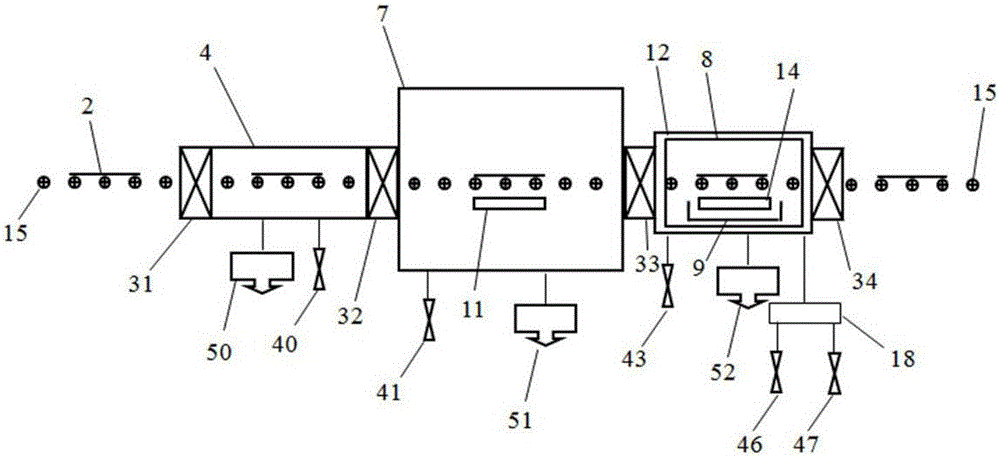
[0057] see figure 2 , the equipment for continuously preparing two-dimensional nano-films of the present invention comprises: a feed chamber 4, a sample preparation chamber 7, and a discharge chamber 12; The chambers 12 are all provided with belt pulleys 15 for transferring samples; the feeding chamber 4 is provided with a valve 31 communicating with the atmosphere, a valve 32 is provided between the feeding chamber 4 and the sample preparation chamber 7, and the sample preparation chamber 7 is connected to the outlet chamber. A valve 33 is provided between the material chambers 12, and a valve 34 communicating with the atmosphere is provided in the discharge chamber 12; the feed chamber 4, the sample preparation chamber 7 and the discharge chamber 12 are connected into one by a belt pulley and a valve. overall.

[0058] The sample preparation chamber 7 is provided with a second heating device 11 , and the discharge chamber 12 is provided with a third heating device 14 .

...

Embodiment 3

[0065] see image 3 , the equipment for continuously preparing two-dimensional nano-films of the present invention comprises: a feed chamber 4, a sample preparation chamber 7, and a discharge chamber 12; The chambers 12 are all equipped with rollers 1 for transferring samples; the feeding chamber 4 is provided with a valve 31 connected to the atmosphere, and a valve 32 is arranged between the feeding chamber 4 and the sample preparation chamber 7, and the sample preparation chamber 7 is connected to the outlet chamber. A valve 33 is provided between the material chambers 12, and a valve 34 connected to the atmosphere is provided in the discharge chamber 12; the feed chamber 4, the sample preparation chamber 7 and the discharge chamber 12 are connected into one by rollers and valves. overall.

[0066] The feeding chamber 4 is provided with a first surface processor 5 , the sample preparation chamber 7 is provided with a second heating device 11 , and the discharging chamber 12...


PUM


Abstract

The invention discloses a device for continuously preparing two-dimensional nano tin films. The device comprises a feed chamber, a sample preparing chamber, a discharge chamber, and the like, wherein valves are arranged among the chambers; samples are conveyed among the chambers through conveying devices such as rollers or conveying belts; each chamber is connected with an independent vacuumizing device and an independent air pipeline; the sample preparing chamber is provided with a physical vapor deposition system, a chemical vapor deposition system, and the like; the feed chamber can be provided with a heating device or a plasma surface treatment system; and the discharge chamber can be provided with a heating device, and the like. According to the device, the whole device is provided with an automated control system for controlling the switching on and switching off of the valves among the chambers, sample transmission, operation of a vacuum system, gas flow, and the like; and the structure is simple, the working is reliable, a uniform graphene, transition metal sulfide, silylene, germylene or boron nitride two-dimensional nano tin film, and the like, can be continuously prepared in a large area, and the device is applicable to industrialized preparation of two-dimensional nano tin films.

Description

[0001] The patent application for this invention is accepted by the State Intellectual Property Office of the People's Republic of China. Application number: 201210095936.8, application date: April 02, 2012, applicant: Xu Mingsheng, invention name: a device for continuously preparing two-dimensional nano-films case application. technical field [0002] The invention relates to equipment for preparing two-dimensional nanometer films, in particular to equipment for continuously preparing two-dimensional nanometer membranes. Background technique [0003] Two-dimensional nanofilm refers to a new class of materials with two-dimensional planar features, also known as two-dimensional layered materials or two-dimensional crystals. The most typical two-dimensional layered material is the graphene film discovered in 2004[ Science 306,666 (2004), Nature 438,197(2005)]; previous theoretical studies believed that two-dimensional materials could not exist in reality due to thermodynami...

Claims


Application Information

Patent Timeline
IPC IPC(8): C23C14/56C23C16/54
CPCC23C14/56C23C16/54C23C14/0623C23C14/0647C23C14/0605C23C14/48C23C14/568
Inventor 徐明生
Owner 徐明生
Learn More