
A device and method for manufacturing an organic light emitting display

A light-emitting display, organic technology, applied in the direction of copying/marking methods, electric solid devices, devices for coating liquids on surfaces, etc., can solve the problems of dripping other positions or other pixels, large errors, etc. The effect of bias

Active Publication Date: 2018-01-30
TCL CHINA STAR OPTOELECTRONICS TECH CO LTD
View PDF6 Cites 0 Cited by
  • Summary
  • Abstract
  • Description
  • Claims
  • Application Information

AI Technical Summary

Problems solved by technology

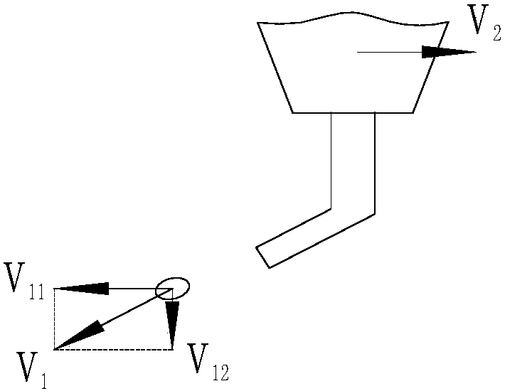
[0003] When the luminescent layer is formed by inkjet printing, the ink will have a uniform speed along the moving direction of the nozzle after being ejected from the nozzle, and at the same time, there will be a downward acceleration g to accelerate downward, so the ink will be thrown flat or obliquely , so when inkjet is being performed, the ink in the nozzle needs to fall a certain distance in advance, so that the error of the ink dropping in the center of the pixel area is relatively large, which may cause the risk of dropping to other positions or other pixels

Method used


Image

  • A device and method for manufacturing an organic light emitting display
  • A device and method for manufacturing an organic light emitting display
  • A device and method for manufacturing an organic light emitting display

Examples


Embodiment Construction

[0020] In order to further illustrate the technical means and effects adopted by the present invention, the following describes in detail in conjunction with the embodiments of the present invention and the accompanying drawings.

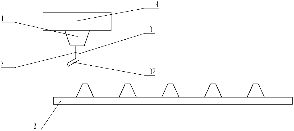
[0021] refer to figure 1 , figure 1 It is a structural schematic diagram of the first embodiment of the manufacturing equipment of an organic light-emitting display according to the present invention. In this embodiment, it includes: a shower head 1 for placing on a substrate 2 and including at least one nozzle 3. The nozzle 3 is used for The ink is ejected to the surface of the substrate 2; the moving unit 4 is used to control the relative movement of the nozzle 1 and the substrate 2.

[0022] In this embodiment, the moving unit 4 controls the shower head 1 to move relative to the substrate 2 along a direction parallel to the surface of the substrate 2 . In other embodiments, the moving unit 4 controls the shower head 1 to move relative to the su...


PUM


Abstract

The invention discloses a manufacturing device and method of an organic light-emitting display. The device includes: a nozzle for placing on a substrate and including at least one nozzle for ejecting ink to the surface of the substrate; a moving unit, It is used to control the relative movement of the nozzle and the substrate; wherein, during the process of ejecting ink from the nozzle, the ejection speed of the nozzle to the ink has a first velocity component in the direction parallel to the surface of the substrate, and the relative movement between the nozzle and the substrate The movement velocity has a second velocity component in a parallel direction, and the first velocity component and the second velocity component are opposite to each other. In the present invention, the first velocity component of the ejection velocity of the nozzle in the parallel direction to the surface of the substrate is opposite to the second velocity component of the relative moving velocity of the nozzle and the substrate in the parallel direction, thereby making the ink relatively Accurately drop on the designated area, effectively improving the problem of inkjet printing deviation.

Description

technical field [0001] The invention relates to the field of manufacturing organic light emitting displays, in particular to a device and a manufacturing method for manufacturing organic light emitting displays. Background technique [0002] A display that displays various information on a screen is a core technology of the information and telecommunication age, and the display is developed to be thinner, lighter, portable, and high-performance. Accordingly, flat panel displays, such as organic light emitting displays, which can overcome various disadvantages of cathode ray tubes (CRTs), ie, weight and volume, have attracted much attention. Organic light emitting displays are self-emitting devices that use a thin organic light emitting layer between electrodes. Organic light-emitting displays can be made as thin as paper. Organic light emitting displays can be classified into small molecule organic light emitting displays and polymer organic light emitting displays accordi...

Claims


Application Information

Patent Timeline
Patent Type & Authority Patents(China)
IPC IPC(8): B41J2/01B41M5/00H10K99/00
CPCB41J2/01B41M5/0047B05B13/04B05B12/16H10K71/135H10K71/00B05C11/10
Inventor 石龙强
Owner TCL CHINA STAR OPTOELECTRONICS TECH CO LTD
Learn More