
Automatic gas valve assembly line

A gas valve and assembly line technology, which is applied in the direction of assembly machines, measuring devices, instruments, etc., can solve the problems of increasing the difficulty of production management, affecting product reliability and cost rate, and low processing efficiency, so as to reduce labor costs and human factors. The impact of products, improving production assembly efficiency and detection accuracy, and realizing the effect of automated production

Active Publication Date: 2016-07-20
COPRECI COMPONENT ZHUHAI CO LTD
View PDF8 Cites 18 Cited by
  • Summary
  • Abstract
  • Description
  • Claims
  • Application Information

AI Technical Summary

Problems solved by technology

In the prior art, the assembly of gas valves is generally divided into two types: manual assembly and equipment assembly. The cost of pure manual assembly is low, but due to the greatest influence of human factors, its processing efficiency is low and installation errors are prone to occur. , Excessive error and other phenomena seriously affect the reliability and cost rate of the product; equipment assembly can solve these problems well, but the gas valve assembly equipment at the present stage is set independently, and each installation process needs to be installed The semi-finished product is transported to the next equipment, which undoubtedly increases the difficulty of production management, and it is easy to cause damage to the product during the transportation process, and the positioning of each new equipment is different, prone to production errors; and The production assembly equipment and testing equipment are separated, which has a great impact on the management and production of the enterprise, and greatly slows down the production efficiency

Method used


Image

  • Automatic gas valve assembly line
  • Automatic gas valve assembly line
  • Automatic gas valve assembly line

Examples


Embodiment Construction

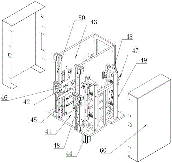
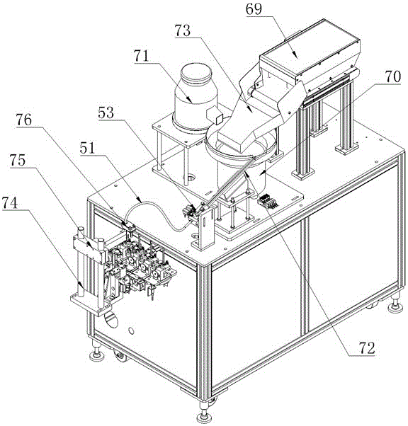
[0026] Such as Figure 1 to Figure 12 As shown, the present invention includes a frame body 1, an assembly part and a detection part arranged on the frame body 1, a connecting conveyor belt 2 is arranged between the assembly part and the detection part, and a connecting conveyor belt 2 is arranged in the assembly part. There is a closed-loop conveyor belt, and the assembly part includes an inner nozzle assembly station 3, a valve core loading station 4, a spring feeding station 5, a valve cover installation station 6, and a screwing station 7, and the inner nozzle assembly station Between the station 3 and the valve core feeding station 4, between the valve core feeding station 4 and the spring feeding station 5, a valve body blowing station 35 and a grease filling station are respectively arranged. Station 36 and uniform grease station 8 are also provided with a spring detection station 9 and a screw detection station 31 beside the screw station 7, and an LP nozzle installati...


PUM


Abstract

The invention discloses and provides an automatic gas valve assembly line. By the adoption of the automatic gas valve assembly line, automatic assembly and detection integration of gas valves can be achieved, and the production and assembly efficiency and the detection accuracy of the gas valves are effectively improved. The automatic gas valve assembly line comprises a frame body, an assembly part and a detection part, wherein the assembly part and the detection part are arranged on the frame body. A connection conveying belt is arranged between the assembly part and the detection part. A closed-loop conveying belt is arranged in the assembly part. The assembly part comprises an inner spray nozzle assembly station, a valve core feeding station, a spring feeding station, a valve deck installation station and a screwing station. A valve body blowing-off station, a grease filling station and a grease uniform-rotation station are arranged between the inner spray nozzle assembly station and the valve core feeding station as well as between the valve core feeding station and the spring feeding station correspondingly. A spring detection station and a screw detection station are further arranged beside the screwing station. An LP spray nozzle installation station is arranged in the position of the connection conveying belt. A comprehensive detection device is arranged on the detection part.

Description

technical field [0001] The invention relates to an automatic production line, in particular to an automatic assembly line for gas valves which is applied to the integration of automatic assembly and detection of gas valves. Background technique [0002] The gas valve is a control component in the gas delivery system, which has the functions of cut-off, regulation, flow diversion, reverse flow prevention, pressure stabilization, flow diversion or overflow pressure relief. Gas valves used in gas control systems range from the simplest cut-off valves to various gas valves used in extremely complex automatic control systems, with a wide variety of varieties and specifications. In the prior art, the assembly of gas valves is generally divided into two types: manual assembly and equipment assembly. The cost of pure manual assembly is low, but due to the greatest influence of human factors, its processing efficiency is low and installation errors are prone to occur. , Excessive er...

Claims


Application Information

Patent Timeline
IPC IPC(8): B23P21/00G01D21/02B07C5/00B07C5/34B07C5/38
CPCB07C5/00B07C5/34B07C5/38B07C2501/0063B23P21/004G01D21/02
Inventor 黄世海
Owner COPRECI COMPONENT ZHUHAI CO LTD
Learn More