Rotary welding device

A welding device and rotary technology, applied in welding equipment, resistance welding equipment, transportation and packaging, etc., can solve the problems of lower welding yield and welding efficiency, sticking needle phenomenon, unsightly surface, etc., and improve the quality of welding process , meet high technical requirements, overcome the effect of sticking needle phenomenon

Active Publication Date: 2017-11-21
UNION ELECTRIC DALIAN CO LTD
View PDF8 Cites 0 Cited by
  • Summary
  • Abstract
  • Description
  • Claims
  • Application Information

AI Technical Summary

Problems solved by technology

[0002] In the production process of new energy vehicle battery packs and other electronic components, welding equipment is commonly used production equipment. According to the needs of production, resistance welding is often used between workpieces. Most of the welding devices in the prior art use parallel welding. Welding, due to the uneven energy distribution during welding, most of the heat loss occurs at the contact between the surface of the workpiece and the electrode welding needle during welding, so that the workpiece and the electrode welding needle stick together, causing the phenomenon of sticking needles. When the welding is completed, the welding head with The upward movement of the stroke cylinder will tear the electrode welding needle and the workpiece. The surface is not beautiful, which affects the welding strength, and it is easy to short-circuit the welding power supply, reducing the welding yield and welding efficiency.

Method used


Image

  • Rotary welding device
  • Rotary welding device

Examples


Embodiment Construction

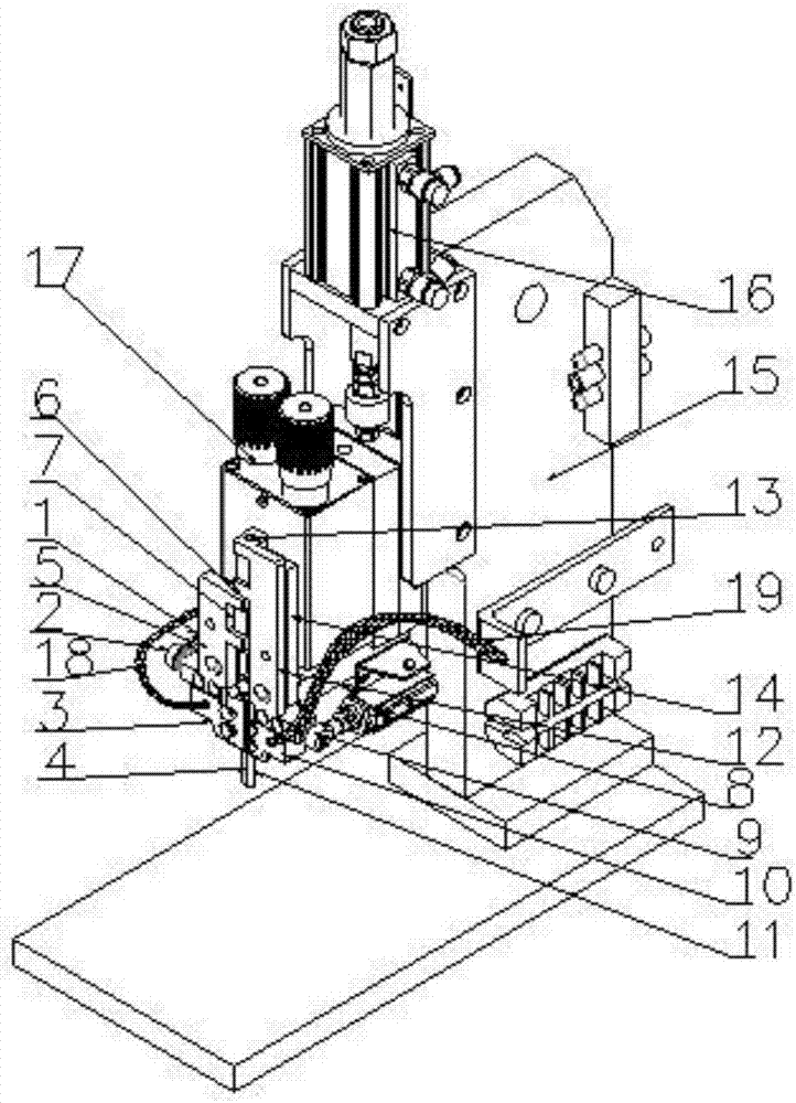
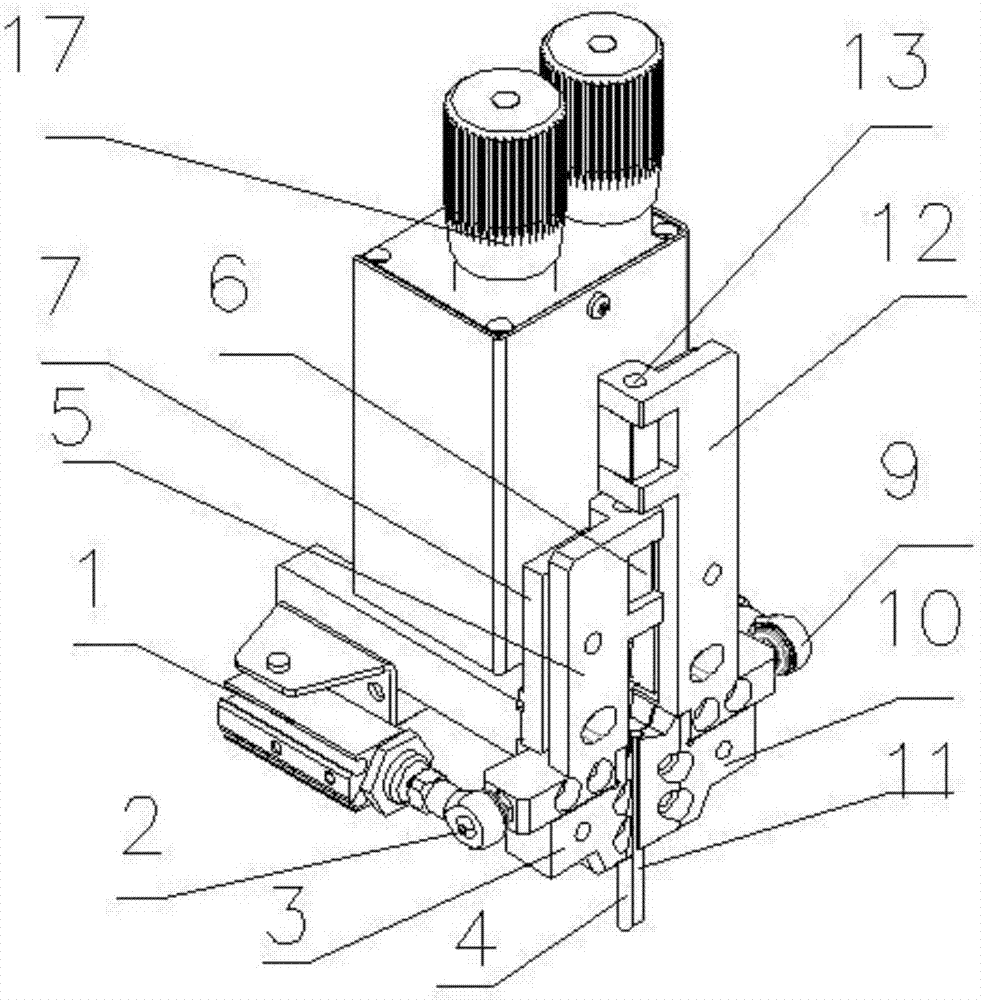
[0020] The present invention will be further described below in conjunction with the accompanying drawings. Such as Figure 1-2 As shown, a rotary welding device includes a bracket main body 15, a welding head 17 and a stroke cylinder 16, the left and right sides of the welding head 17 are respectively equipped with a small cylinder A1 and a small cylinder B8, and the center of the front side of the welding head 17 A fixed hinge A7 and a fixed hinge B14 are respectively installed on both sides of the line; the fixed hinge A7 is connected to the rotary hinge A5 through the rotating shaft A6, and the rotary hinge A5 is connected to the small cylinder A1 through the movable joint A2; The bottom of the above-mentioned rotary hinge A5 is connected with the electrode holder A3; the above-mentioned electrode holder A3 clamps the electrode welding pin A4; the above-mentioned fixed hinge B14 is connected to the rotary hinge B12 through the rotating shaft B13, B12 is connected with the...


PUM


Abstract

The invention discloses a rotary welding device. The rotary welding device comprises a support body, a welding head and a stroke cylinder. Small air cylinders are disposed on the left side and the right side of the welding head correspondingly; fixed hinges are disposed on the two sides of a center line of the front side of the welding head correspondingly; the fixed hinges are connected with rotary hinges through rotary shafts; the rotary hinges are connected with the small air cylinders through movable joints; the lower portions of the rotary hinges are connected with electrode clamps; and the electrode clamps clamp electrode welding pins. According to the rotary welding device, before the stroke cylinder moves upwards, the small air cylinders push the rotary hinges to drive the corresponding electrode clamps and the corresponding electrode welding pins to rotate, and the electrode welding pins are rigidly disconnected around the surfaces of workpieces, so that adhesion between the electrode welding pins and the workpieces is avoided and the situation that the workpieces are pulled broken after pin adhesion is avoided; and the welding appearance is neat, the welding process quality is improved, and high technical requirements in current production are met. By means of the rotary welding device, switching of single-side welding or double-side welding of the workpieces can be achieved.

Description

technical field [0001] The invention relates to the technical field of welding devices, in particular to a rotary welding device. Background technique [0002] In the production process of new energy vehicle battery packs and other electronic components, welding equipment is commonly used production equipment. According to the needs of production, resistance welding is often used between workpieces. Most of the welding devices in the prior art use parallel welding. Welding, due to the uneven energy distribution during welding, most of the heat loss occurs at the contact between the surface of the workpiece and the electrode welding pin during welding, so that the workpiece and the electrode welding pin stick together, causing sticking. The upward movement of the stroke cylinder will tear the electrode welding needle and the workpiece. The surface is not beautiful, which affects the welding strength, and it is easy to short-circuit the welding power supply, reducing the weldi...

Claims


Application Information

Patent Timeline
Patent Type & Authority Patents(China)
IPC IPC(8): B23K11/30B23K11/31B23K11/36
CPCB23K11/30B23K11/31B23K11/36B23K2101/006
Inventor 木下雄一郎
Owner UNION ELECTRIC DALIAN CO LTD
Why Eureka
Try Eureka