
Multifunctional reflow soldering device and control method thereof

A reflow soldering and multi-functional technology, applied in the direction of auxiliary devices, manufacturing tools, welding equipment, etc., can solve the problems of manual repair soldering, high temperature resistance of components, and large manual labor, so as to reduce energy loss and save energy , easy-to-implement effect

Inactive Publication Date: 2016-07-20
东莞市创威自动化科技有限公司
View PDF10 Cites 8 Cited by
  • Summary
  • Abstract
  • Description
  • Claims
  • Application Information

AI Technical Summary

Problems solved by technology

In addition, wave soldering is suitable for hand plug-in boards and dispensing boards, and all components are required to be heat-resistant. There must be no components with SMT solder paste on the surface of the wave peak. weld
2. There are many welding defects. After the post-test, if missing welding is found, manual repair welding is required, which requires a large amount of manual labor.
3. The required components have high temperature resistance
4. Waste of energy, consume a lot of solder bar and flux every day

Method used


Image

  • Multifunctional reflow soldering device and control method thereof
  • Multifunctional reflow soldering device and control method thereof
  • Multifunctional reflow soldering device and control method thereof

Examples


Embodiment 1

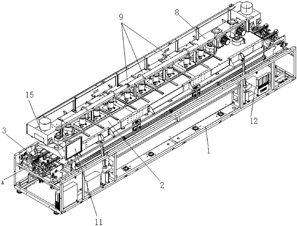
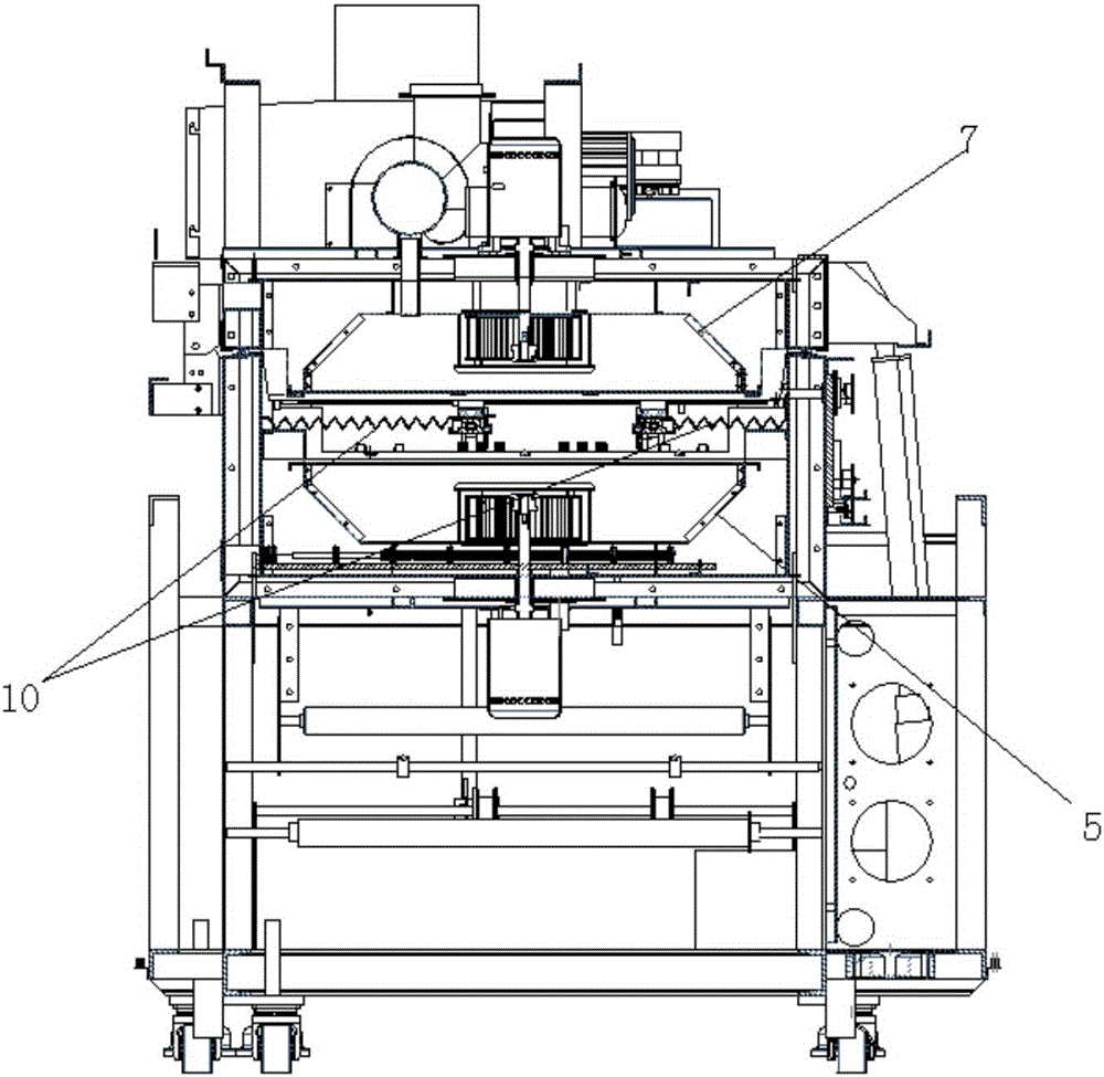
[0036] Example 1: as figure 1 , figure 2 , image 3 , Figure 4 , Figure 5 , Image 6 , Figure 7 , Figure 8 and Figure 11 As shown, a multifunctional reflow soldering device includes a reflow soldering machine table 1, and a soldering machine table cover 2 that can be opened and closed is provided on the rear edge of the upper plane of the reflow soldering machine table 1, and the soldering machine table cover 2 is composed of a can The telescopic support arm is connected and controlled to open or close. The upper plane of the reflow soldering machine 1 is provided with a product conveying line 3 whose width can be adjusted. The reflow soldering machine 1 is sequentially provided with two upwardly blowing hot air from left to right. The lower furnace 4 and a second lower furnace 5 blowing upwards, the position corresponding to the first lower furnace 4 in the welding machine cover 2 is provided with a first temperature zone upper furnace 6 for air extraction, and t...

Embodiment 2

[0047] Embodiment 2: a multifunctional reflow soldering device, comprising a reflow soldering machine table 1, a soldering machine table cover 2 that can be opened and closed is provided on the rear edge of the upper plane of the reflow soldering machine table 1, and the soldering machine table cover 2 is composed of a The telescopic support arm is connected to control the opening or closing. The upper plane of the reflow soldering machine 1 is provided with a product conveying line 3 whose width can be adjusted. The lower furnace 4 and a second lower furnace 5 blowing upward, the welding machine cover 2 is provided with a first temperature zone upper furnace 6 for air extraction at the position corresponding to the first lower furnace 4, and the welding machine cover The position corresponding to the second lower furnace 5 in 2 is provided with a second temperature zone upper furnace 7 that blows hot air downward, the first temperature zone upper furnace 6 and the first lower ...

Embodiment 3

[0048] Embodiment 3: A control method of a multifunctional reflow soldering device, comprising the following steps:

[0049] A) Control the temperature zone, set the first temperature zone (preheating zone), the second temperature zone (reflow soldering zone) and the cooling zone which can be reflowed; The furnace is formed, and the second temperature zone is formed by the upper furnace and the second lower furnace in the second temperature zone; in the upper furnace of the second temperature zone, there is a heating wire that can control heating or turn off the heating independently; The furnace is blown hot air, and the cooling area is blown cold air;

[0050] B) Set the temperature value of the first temperature zone and the second temperature zone, and sense the temperature value of the temperature zone through the temperature sensor, so that the temperature between the upper furnace and the first lower furnace in the first temperature zone of the first temperature zone is...


PUM


Abstract

The invention discloses a multifunctional reflow soldering device. The multifunctional reflow soldering device comprises a reflow soldering machine platform. A soldering machine platform cover which can be opened and closed is arranged at the back edge of the upper plane of the reflow soldering machine platform. The upper plane of the reflow soldering machine platform is provided with a product conveying line adjustable in width. The reflow soldering machine platform is internally provided with first lower furnace pipes and second lower furnace pipes from left to right in sequence. A first warm area upper furnace pipe used for air draft is arranged in the position, corresponding to each first lower furnace pipe, of the interior of the soldering machine platform cover. A second warm area upper furnace pipe blowing hot air or cold air downwards is arranged in the position, corresponding to each second lower furnace pipe, of the interior of the soldering machine platform cover. Each first warm area upper furnace pipe and the corresponding first lower furnace pipe form a first warm area. Each second warm area upper furnace pipe and the corresponding second lower furnace pipe form a second warm area. Air blocking curtains which are used for separating the cold air from the hot air and can be stretched or shortened are arranged in the positions, located between the first warm areas and the second warm areas, of the product conveying line. The reflow soldering machine platform is provided with a man-machine control interface and further provided with a cooling area. Each second warm area upper furnace pipe is internally provided with a second warm area upper furnace pipe heating wire for independently controlling heating. According to the multifunctional reflow soldering device, the function of soldering SMT boards and PCB through holes can be achieved.

Description

technical field [0001] The invention relates to circuit board welding equipment, in particular to a multifunctional reflow soldering device. Background technique [0002] At present, in the soldering technology of circuit boards, the commonly used soldering equipment is "wave soldering". Wave soldering is to dissolve the tin bar into a liquid state through a tin bath, and use the motor to stir to form a wave crest, so that the PCB and the parts are welded together. It is generally used in Soldering of hand inserts and glue board for smt. Reflow soldering is mainly used in the SMT industry. It melts the solder paste printed on the PCB and welds the parts through hot air or other heat radiation conduction. However, there are some defects in the baking and heating method of wave soldering: 1. Flux should be sprayed first in wave soldering, and then preheating, welding and cooling zone should be carried out. Reflow soldering passes through the preheating zone, the reflow zone,...

Claims


Application Information

Patent Timeline
IPC IPC(8): B23K1/012B23K1/20B23K3/00B23K3/08B23K101/42
CPCB23K1/012B23K1/20B23K3/00B23K3/08B23K3/085B23K2101/42
Inventor 王军涛苏金财贾夫振冼志军
Owner 东莞市创威自动化科技有限公司
Learn More