A hydraulic switching device applied to the processing of disk parts

A technology of hydraulic switching device and disc-type parts, applied in the direction of chuck, etc., can solve the problems of inability to guarantee processing safety and efficiency, out-of-tolerance tolerance of parts, and workpiece clamping deformation, so as to eliminate deformation and realize pressure relief. The effect of processing and improving production efficiency

Active Publication Date: 2018-03-13
宁波东力股份有限公司
View PDF6 Cites 0 Cited by
  • Summary
  • Abstract
  • Description
  • Claims
  • Application Information

AI Technical Summary

Problems solved by technology

[0002] When using JXCK50*350 CNC lathe to process disc parts, such as bearing inner and outer covers and end covers, the clamping force of the hydraulic chuck is too large, resulting in workpiece clamping deformation. After processing, the parts are all qualified when they are not unloaded. , when the part is unloaded from the processing garage, the shape and position tolerance of the part is out of tolerance
However, if the hydraulic clamping force is reduced, the workpiece will fly out during rough turning, which cannot guarantee the safety and efficiency of processing

Method used


Image

  • A hydraulic switching device applied to the processing of disk parts
  • A hydraulic switching device applied to the processing of disk parts
  • A hydraulic switching device applied to the processing of disk parts

Examples


Embodiment Construction

[0031] Hereinafter, embodiments of the present invention will be described with reference to the drawings. In the embodiments, parts of the same configuration are given the same reference numerals and descriptions are omitted.

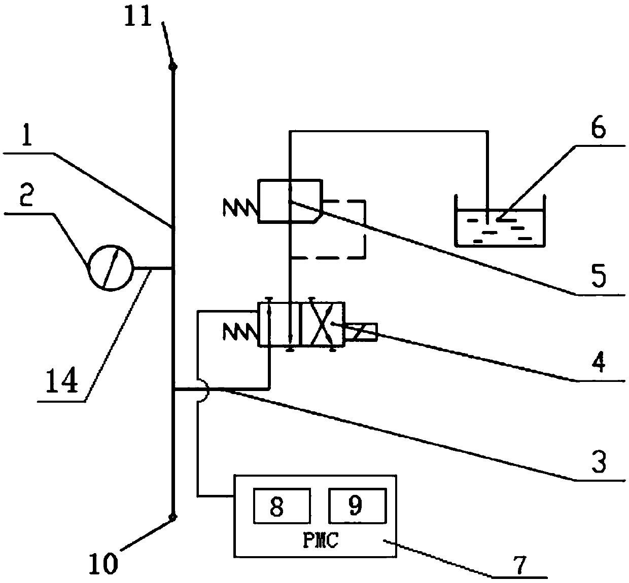
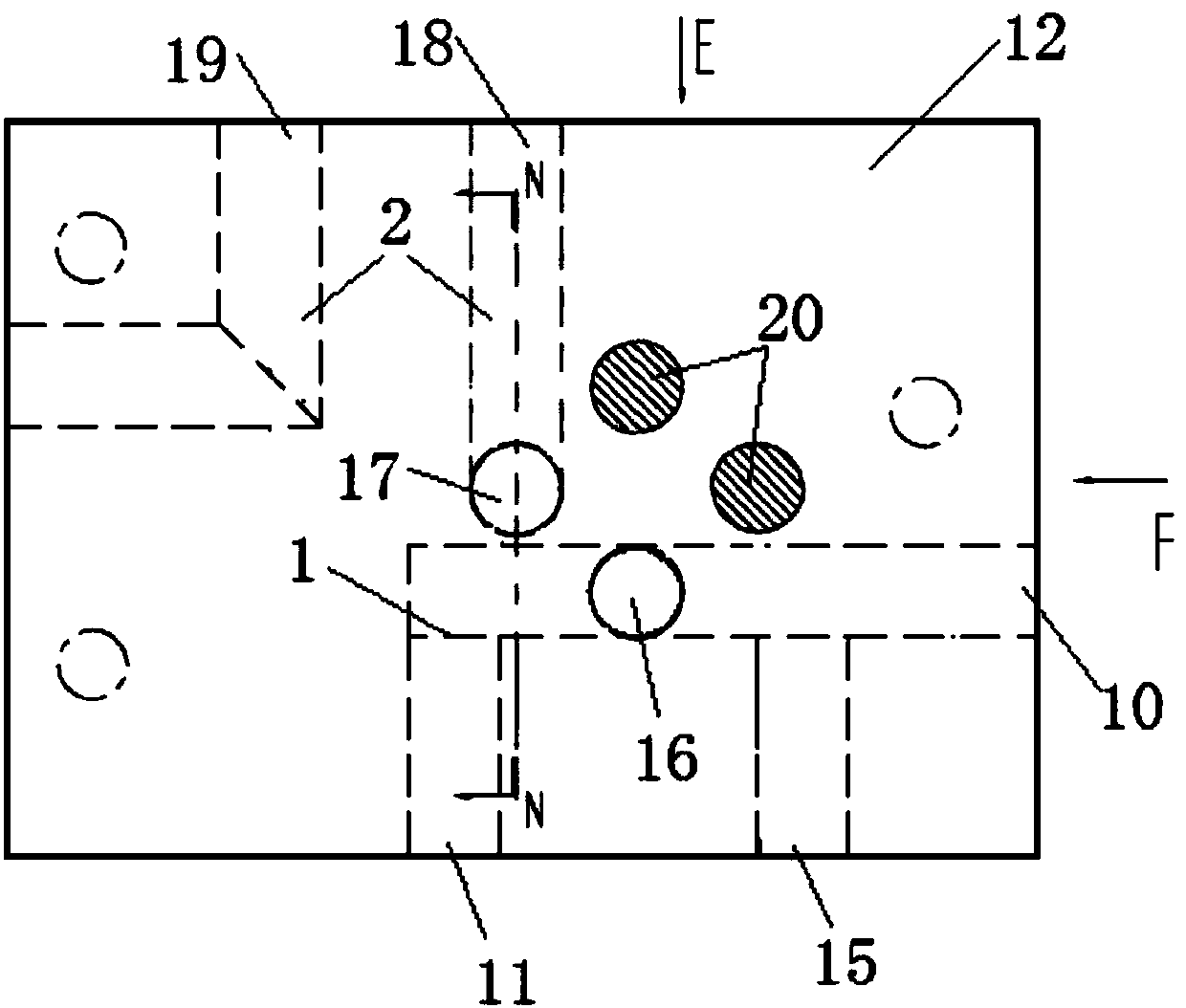
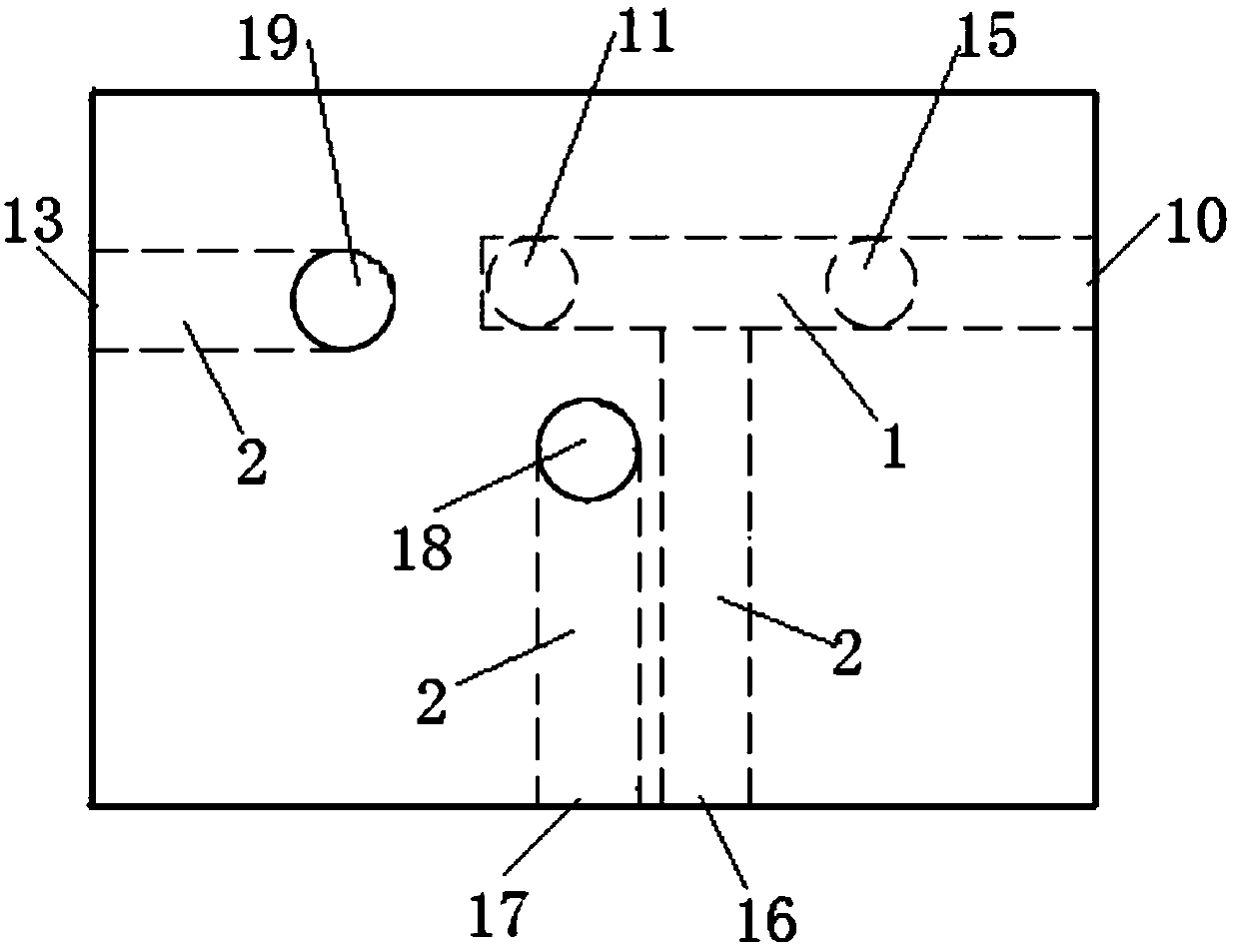
[0032] refer to figure 1 , is a structural schematic diagram of the hydraulic switching device applied to the processing of disk parts according to the present invention; and Figure 2a , is a structural schematic diagram of the distributor 12 of the hydraulic switching device applied to the processing of disk parts according to the present invention.

[0033] As shown in the figure, the hydraulic switching device is installed in an external machine tool for parts processing, including a distributor 12, a solenoid valve 4, and an overflow valve 5.

[0034] The distributor 12 is provided with a first oil passage 1 and a second oil passage 2 in communication. The outlets at both ends of the first oil passage 1 are the oil inlet 10 and the oil outlet 11...


PUM


Abstract

The invention discloses a hydraulic switching device applicable to disc part processing. The hydraulic switching device is mounted in an external machine tool of part processing, and comprises a distributer, an electromagnetic valve and an overflow valve, wherein a first oil way and a second oil way which communicate with each other are arranged in the distributer; the two ends of the first oil way are an oil inlet and an oil outlet; the oil inlet receives hydraulic oil and the hydraulic oil flows into a chuck cylinder; the electromagnetic valve and the overflow valve are mounted on the outer side surface of the distributer, and are sequentially positioned in a hydraulic oil circulation path of the second oil way; an unloading port communicates with a hydraulic station of the external machine tool; the electromagnetic valve is electrically connected with a PMC controller in the external machine tool; a first built-in relay and a second built-in relay are arranged inside the PMC controller for controlling the turn-on and turn-off of the electromagnetic valve; and the PMC controller has a program for automatically controlling the operation of the relays inside. According to the technical scheme, the high and low pressure states of hydraulic oil can be automatically switched, the deformation of disc parts after processing is eliminated, the processing safety is guaranteed, and the production efficiency is improved.

Description

technical field [0001] The invention relates to the technical field of CNC machine tool parts processing equipment components, in particular to a hydraulic switching device applied to the processing of disk parts. Background technique [0002] When using JXCK50*350 CNC lathe to process disc parts, such as bearing inner and outer covers and end covers, the clamping force of the hydraulic chuck is too large, resulting in workpiece clamping deformation. After processing, the parts are all qualified when they are not unloaded. , when the part is unloaded from the processing garage, the shape and position tolerance of the part is out of tolerance. However, if the hydraulic clamping force is reduced, the workpiece will fly out during rough turning, which cannot guarantee the safety and efficiency of processing. [0003] Therefore, in order to eliminate the deformation of disc parts after processing, ensure processing safety and improve production efficiency, it is necessary to au...

Claims


Application Information

Patent Timeline
Patent Type & Authority Patents(China)
IPC IPC(8): B23B31/30B23B31/28
CPCB23B31/28B23B31/30
Inventor 姚丽新俞顶峰童延杰殷炜隽
Owner 宁波东力股份有限公司
Why Eureka
Try Eureka