Cutting device

A technology for cutting devices and components, which is applied in the direction of shearing devices, operating devices, and attachments of shearing machines, etc. It can solve problems such as difficult fixing of knives or replacement of pressing components, time-consuming cleaning operations, and influence on bar cutting accuracy. Achieve the effect of eliminating bounce and easy replacement

Active Publication Date: 2016-07-13
MANYO
View PDF9 Cites 2 Cited by
  • Summary
  • Abstract
  • Description
  • Claims
  • Application Information

AI Technical Summary

Problems solved by technology

Therefore, if a large upward reaction force acts on the pressing member from the bar when cutting the bar, the bar will resist the pressing force of the hydraulic cylinder and swing slightly with the fulcrum as the fulcrum, so the bar will bounce slightly, Concerns about adverse effects on bar cutting accuracy
In addition, since the lever covers the fixed knife or the pressing member from above, it is difficult to replace the fixed knife or the pressing member, and cleaning around the fixed knife or the pressing member takes time.

Method used


Image

  • Cutting device
  • Cutting device
  • Cutting device

Examples


Embodiment Construction

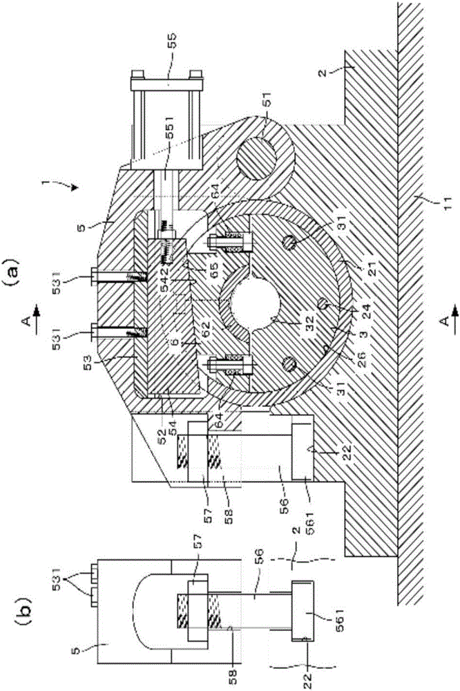
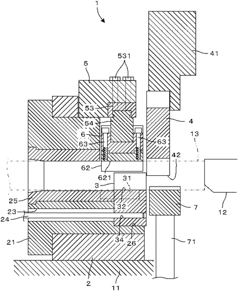
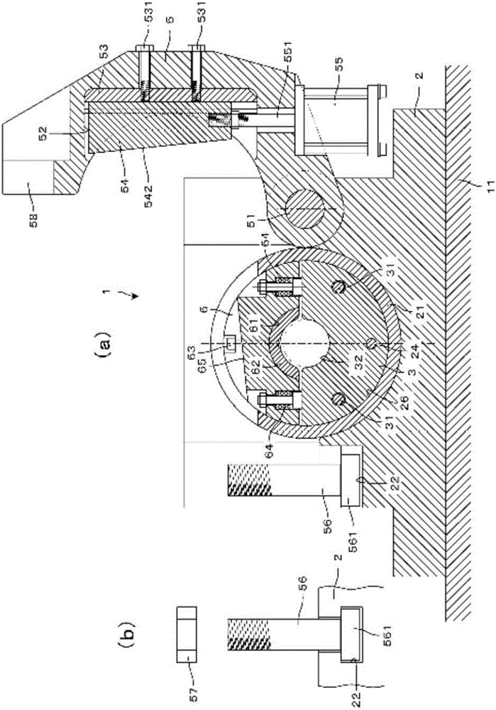
[0036] Embodiments of the present invention will be described below based on the drawings. figure 1 (a) is a longitudinal sectional front view showing a cutting device according to an embodiment of the present invention, figure 1 (b) is the bolt that fixes the clamping rod to the abutment figure 1 (a) Left side view. figure 2 Yes figure 1 The A-A section diagram. image 3 (a) is a longitudinal sectional front view showing a state in which the clamp lever is swung to the replacement position, image 3 (b) is the bolt that fixes the clamping rod to the abutment image 3 (a) Left side view. Figure 4 yes means image 3 (a) is a front view of a longitudinal section in a state where the stationary knife and the pressing member are removed from the abutment. Figure 5 (a) is a front view showing a clamp block and a guide block, Figure 5 (b) is Figure 5 (a) Left side view. Image 6 It is a front view showing the fixed knife and the movable knife.

[0037] like Figure ...


PUM


Abstract

The present invention not only eliminates bouncing of a rod material during cutting but also makes replacement of a stationary blade and a pressing member and cleaning work of the stationary blade and the surrounding of the pressing member easy. A pressing member-side inclined surface (65) of a pressing member (6) is pressed downward by a clamp block-side inclined surface (542) of a clamp block (54), thereby press-clamping a rod material (13) with a pressing section (621) of a pressing bushing (62). The clamp block-side inclined surface (542) and pressing member-side inclined surface (65) are formed so as to have an inclination angle (Theta) of six degrees. Because this inclination angle (Theta) is set to an angle at which a component force of the pressing force becomes smaller than the maximum frictional force generated between the pressing member-side inclined surface (65) and clamp block-side inclined surface (542), the clamp block (54) and a piston rod (551) do not move back leftward (in the unclamping direction) even when a large reaction force has acted upon the pressing member (6) during the cutting of the rod material (13). Bouncing of the rod material (13) during the cutting is eliminated, thereby enabling manufacturing of stable billets with improved cutting precision.

Description

technical field [0001] The present invention relates to a cutting device that presses a rod to cut. More specifically, it relates to a cutting device provided as a cutting device for cutting a billet for forging of a predetermined length from a bar and cutting the bar by shearing, and The bar material sent out to the stationary knife of the cutting device is pressed to cut. Background technique [0002] When producing a forged product or the like as a metal part, first, it is necessary to cut and take out a required length called a billet from a bar material which is the raw material thereof. In the case of a forged product, in a subsequent processing step, the billet is heated in a heating furnace or put into a press mold at room temperature without heating to be plastically processed into a target shape. Typically, after such a forging step, a machining step or the like is performed to produce the final part. Therefore, if the quality of the billet is poor, it will dire...

Claims


Application Information

Patent Timeline
Patent Type & Authority Applications(China)
IPC IPC(8): B23D33/08B21K27/06B23D15/04
CPCB21K27/06B23D15/04B23D33/08
Inventor 越智俊夫
Owner MANYO
Why Eureka
Try Eureka