An automatic deceleration device with identification function
A deceleration device and automatic technology, which is applied in the field of vehicle deceleration, can solve the problems of insufficient perception dimension, poor real-time performance, and low calculation accuracy, and achieve the effect of convenient and precise control, simple structure, economical durability, and strong anti-interference ability
- Summary
- Abstract
- Description
- Claims
- Application Information
AI Technical Summary
Problems solved by technology
Method used
Image

Examples
Embodiment 1
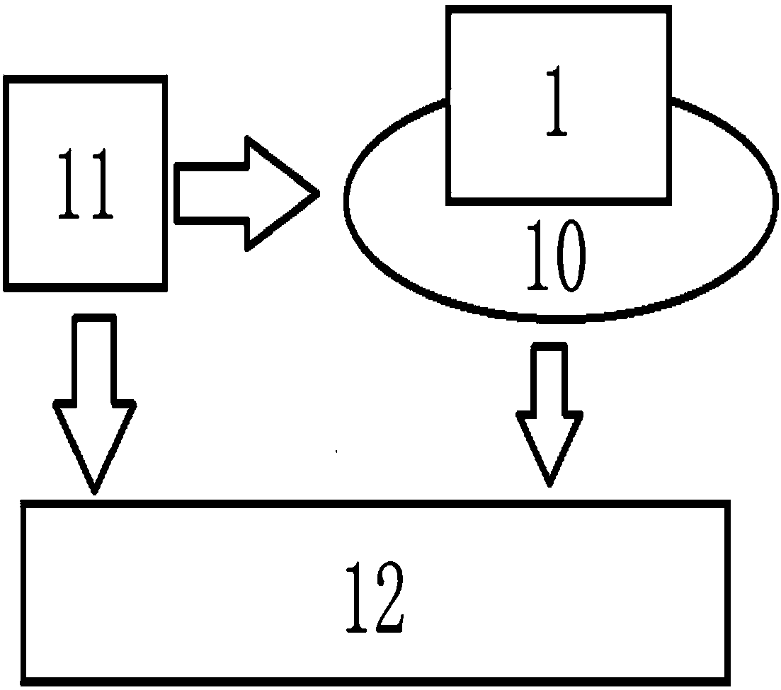
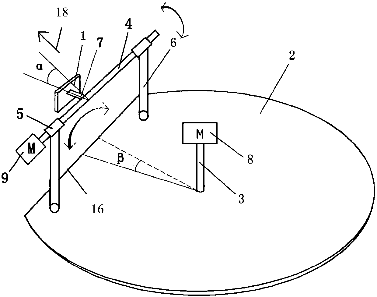
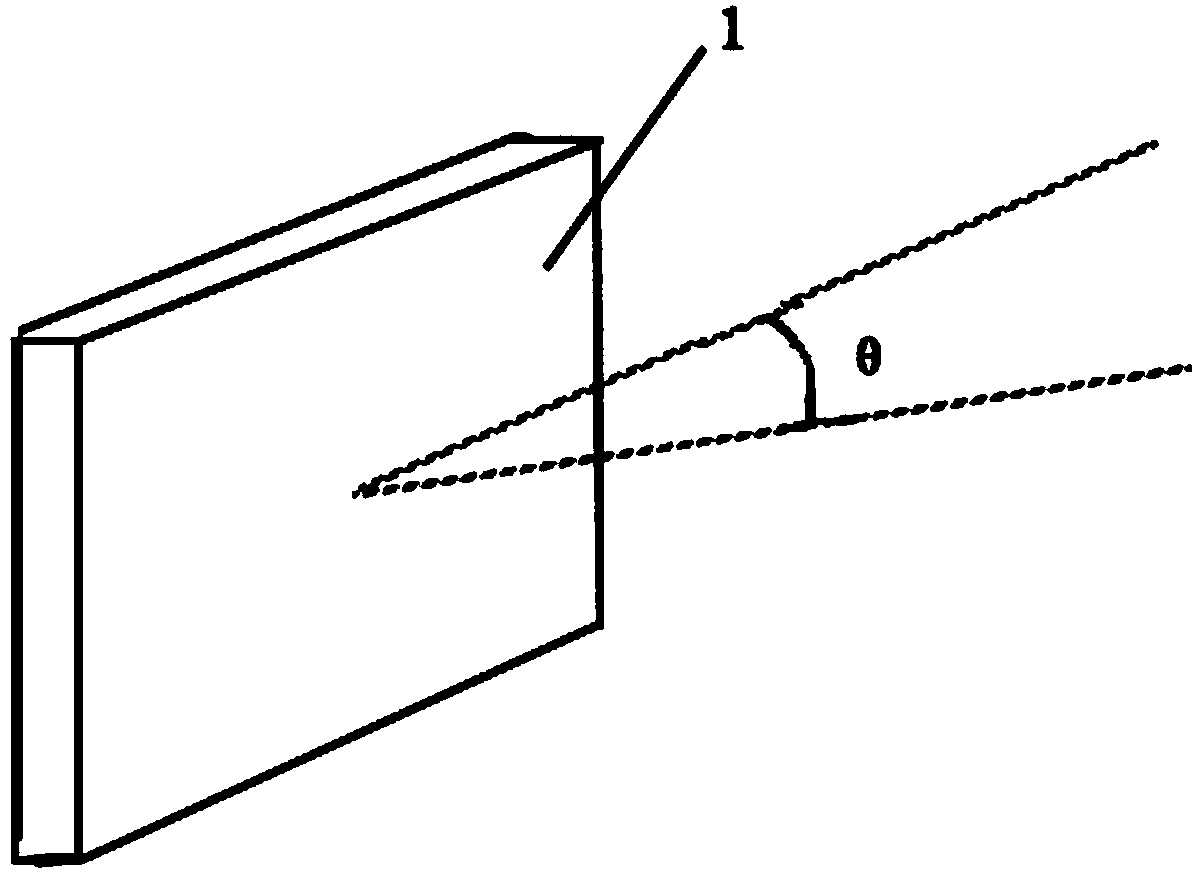
[0033] like Figure 1-4The shown automatic deceleration device with recognition function includes a deceleration device and a millimeter-wave radar three-dimensional environment perception system installed on the deceleration device; the millimeter-wave radar three-dimensional environment perception system includes a millimeter-wave radar 1, a rotating mechanical device 10, a control The unit 11 and the data processing unit 12; the rotating mechanical device includes a first rotating shaft 3, a rotating disk 2 and a second rotating shaft 4, the first rotating shaft 3 is vertically arranged and fixed to the center of the rotating disk 2, the The first rotating shaft 3 is driven to rotate by the first stepping motor 8; the second rotating shaft 4 driven to rotate by the second stepping motor 9 is horizontally sleeved in the bearing seat 5, and the bearing seat 5 is passed through two vertically arranged The support shaft 6 is fixed on the rotating disk 2; a connecting portion 7 ...
Embodiment 2
[0051] like Figure 1-4The shown automatic deceleration device with recognition function includes a deceleration device and a millimeter-wave radar three-dimensional environment perception system installed on the deceleration device; the millimeter-wave radar three-dimensional environment perception system includes a millimeter-wave radar 1, a rotating mechanical device 10, a control The unit 11 and the data processing unit 12; the rotating mechanical device includes a first rotating shaft 3, a rotating disk 2 and a second rotating shaft 4, the first rotating shaft 3 is vertically arranged and fixed to the center of the rotating disk 2, the The first rotating shaft 3 is driven to rotate by the first stepping motor 8; the second rotating shaft 4 driven to rotate by the second stepping motor 9 is horizontally sleeved in the bearing seat 5, and the bearing seat 5 is passed through two vertically arranged The support shaft 6 is fixed on the rotating disk 2; a connecting portion 7 ...
Embodiment 3
[0069] like Figure 1-4The shown automatic deceleration device with recognition function includes a deceleration device and a millimeter-wave radar three-dimensional environment perception system installed on the deceleration device; the millimeter-wave radar three-dimensional environment perception system includes a millimeter-wave radar 1, a rotating mechanical device 10, a control The unit 11 and the data processing unit 12; the rotating mechanical device includes a first rotating shaft 3, a rotating disk 2 and a second rotating shaft 4, the first rotating shaft 3 is vertically arranged and fixed to the center of the rotating disk 2, the The first rotating shaft 3 is driven to rotate by the first stepping motor 8; the second rotating shaft 4 driven to rotate by the second stepping motor 9 is horizontally sleeved in the bearing seat 5, and the bearing seat 5 is passed through two vertically arranged The support shaft 6 is fixed on the rotating disk 2; a connecting portion 7 ...
PUM
 Abstract
Description
Claims
Application Information
 - R&D
- Intellectual Property
- Life Sciences
- Materials
- Tech Scout
- Unparalleled Data Quality
- Higher Quality Content
- 60% Fewer Hallucinations
Browse by: Latest US Patents, China's latest patents, Technical Efficacy Thesaurus, Application Domain, Technology Topic, Popular Technical Reports.
© 2025 PatSnap. All rights reserved.Legal|Privacy policy|Modern Slavery Act Transparency Statement|Sitemap|About US| Contact US: help@patsnap.com