
Full-closed type light trap sensing control unit and manufacturing method therefor

A technology of sensing control and manufacturing method, which is applied in the direction of measuring devices, instruments, measuring acceleration, etc., can solve the problems of large microcavity space, low particle capture efficiency, and inability to achieve stable particle capture for a long time, so as to isolate interference and Pollution, the effect of improving capture efficiency

Active Publication Date: 2016-07-13
ZHEJIANG UNIV
View PDF4 Cites 6 Cited by
  • Summary
  • Abstract
  • Description
  • Claims
  • Application Information

AI Technical Summary

Problems solved by technology

However, at present, the chip-type sensitive units developed by most manufacturers or research institutions are aimed at high-throughput experiments such as chemistry, biology, and medicine. They are semi-sealed chip-type units, which cannot achieve long-term stable capture of particles. particle position detection accuracy
Moreover, the microcavity space of the chip unit used in most space light traps is relatively large, and the particle capture efficiency is not high.

Method used


Image

  • Full-closed type light trap sensing control unit and manufacturing method therefor
  • Full-closed type light trap sensing control unit and manufacturing method therefor
  • Full-closed type light trap sensing control unit and manufacturing method therefor

Examples


Embodiment Construction

[0044] The present invention will be further described below in conjunction with the accompanying drawings.

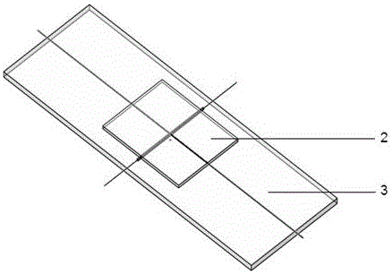
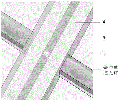
[0045] The invention provides a chip optical trap sensing control unit with high capture efficiency, high optical fiber alignment accuracy, easy processing, assembly and cleaning, such as figure 1 , 2 shown.

[0046] Its manufacturing process can be divided into the assembly of the square capillary 4, the preparation of the PDMS substrate and the overall packaging.

[0047] 1. Assembly of square capillary

[0048] The specific operation steps are:

[0049] 1) Strip the coating of two sections of ultra-fine optical fiber 5 with a diameter of tens of microns (here ultra-fine refers to the diameter of the optical fiber, and the diameter after stripping the coating is about 10-90 microns), and cut with ultra-fine optical fiber 5 Knife handles end faces.

[0050] 2) Use a butane blowtorch to burn off the protective layer on the outside of the square capillary 4, wipe i...


PUM


Abstract

The invention discloses a full-closed type light trap sensing control unit and a manufacturing method therefor. The control unit comprises a cube micro-cavity for storing particles, a PDMS (polydimethylsiloxane) substrate with a common single-mode optical fiber channel, and a glass substrate for sealing. The glass substrate is provided with mark lines, and the mark lines are used for indicating the position of the center of a light trap and guaranteeing the relative position of the cube micro-cavity and the center of the light trap. The manufacturing method comprises the steps: the assembly of a square capillary tube, the preparation of the PDMS substrate, and the overall packaging. The control unit limits the movement range of particles through the micro-cavity, improves the capturing efficiency of particles, and isolates the external pollution and impact through the full-closed design.

Description

technical field [0001] The invention relates to the field of optical accelerometers, in particular to an on-chip integrated device of an optical trap accelerometer. Background technique [0002] The optical trap accelerometer is a branch of the optical accelerometer. It uses the tiny force generated by the light radiation to realize the suspended support for the mass block in the accelerometer, which eliminates various errors caused by the contact support method and reduces environmental sensitivity. sex. With the development of optoelectronic technology, the optical trap accelerometer gradually shows its development potential in high precision, high sensitivity and miniaturization. [0003] The chip optical trap sensing control unit is a crucial component in the optical trap accelerometer. The quality of its design directly affects the working efficiency, measurement accuracy and sensitivity of the optical trap accelerometer. Optical trap accelerometers require high-effi...

Claims


Application Information

Patent Timeline
Patent Type & Authority Applications(China)
IPC IPC(8): G01P15/03
CPCG01P15/032
Inventor 胡慧珠苏鹤鸣李文强舒晓武刘承
Owner ZHEJIANG UNIV
Learn More