Laser gas detection platform with multiple-reflection long-optical-path high-temperature sample chamber
A technology of multiple reflection and gas detection, applied in color/spectral characteristic measurement, measuring device, material analysis through optical means, etc. It can solve the problems such as difficult to adjust the position and angle, difficult to clean the reflector, and difficult to reach the optical path, etc. Achieve the effect of low cost, reduce the cost of structural parts, and high measurement accuracy
- Summary
- Abstract
- Description
- Claims
- Application Information
AI Technical Summary
Problems solved by technology
Method used
Image

Examples
Embodiment 1
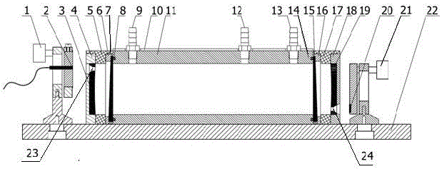
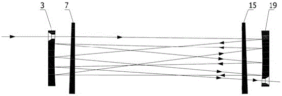
[0061] Example 1: We pass Figure 5 The shown laser emitting device 2 injects and measures NH 3 Corresponding to the laser with a wavelength of 1512nm, turn on the heating device to simulate the on-site environment, such as Figure 6 The optical path adjustment device shown in the figure adjusts the optical path. The emitted light from the laser emitting device 2 enters the inner cavity of the sample chamber housing 11 through the incident window 7, passes through the exit window 15, and then hits the concave reflector 19. After multiple reflections between the conjugate concave reflector 3, the concave reflector 19, the incident window 7, and the exit window 15, the laser light is emitted from the exit of the concave reflector 19 to the laser receiving device 20.
[0062] Such as Figure 7 Shown is the simulated light spot effect diagram, the gas to be detected passes into the sample chamber shell 11 from the gas inlet 9 and is discharged from the gas outlet 13 .
[0063] ...
Embodiment 2
[0066] Embodiment 2: Different from Embodiment 1, since the absorption signal intensity of the gas to be measured is relatively high or the required detection accuracy is low, a long optical path is not required, so a sample that meets the required length of the application is directly used The chamber casing 11 is used as the detection sample chamber. At this time, there is no need to arrange a conjugate laser reflection device in the sample chamber casing 11; and the laser light emitted by the laser emitting device 2 directly enters the sample chamber casing 11, and then the sample chamber casing The other end of 11 is collimated and converged to the laser receiving device 20 after being emitted.
PUM
 Abstract
Description
Claims
Application Information
 - Generate Ideas
- Intellectual Property
- Life Sciences
- Materials
- Tech Scout
- Unparalleled Data Quality
- Higher Quality Content
- 60% Fewer Hallucinations
Browse by: Latest US Patents, China's latest patents, Technical Efficacy Thesaurus, Application Domain, Technology Topic, Popular Technical Reports.
© 2025 PatSnap. All rights reserved.Legal|Privacy policy|Modern Slavery Act Transparency Statement|Sitemap|About US| Contact US: help@patsnap.com