Eureka AIR delivers breakthrough ideas for toughest innovation challenges, trusted by R&D personnel around the world.

Variable-flow single-working medium cascade heat pump system with parallel heat exchangers

A heat pump system and heat exchanger technology, which is applied to compressors with cascade work, fluid circulation arrangements, lighting and heating equipment, etc. The effect of inter-stage energy regulation, simple system structure and high efficiency

Active Publication Date: 2016-07-13
河北航研制冷设备有限公司
View PDF8 Cites 1 Cited by
  • Summary
  • Abstract
  • Description
  • Claims
  • Application Information

AI Technical Summary

Problems solved by technology

However, since the low-temperature working medium is in a supercritical state at room temperature, an expansion vessel is usually installed at the low-temperature stage, the system is complex and it is difficult to realize variable working medium flow control

Method used


Image

  • Variable-flow single-working medium cascade heat pump system with parallel heat exchangers
  • Variable-flow single-working medium cascade heat pump system with parallel heat exchangers
  • Variable-flow single-working medium cascade heat pump system with parallel heat exchangers

Examples


Embodiment 2

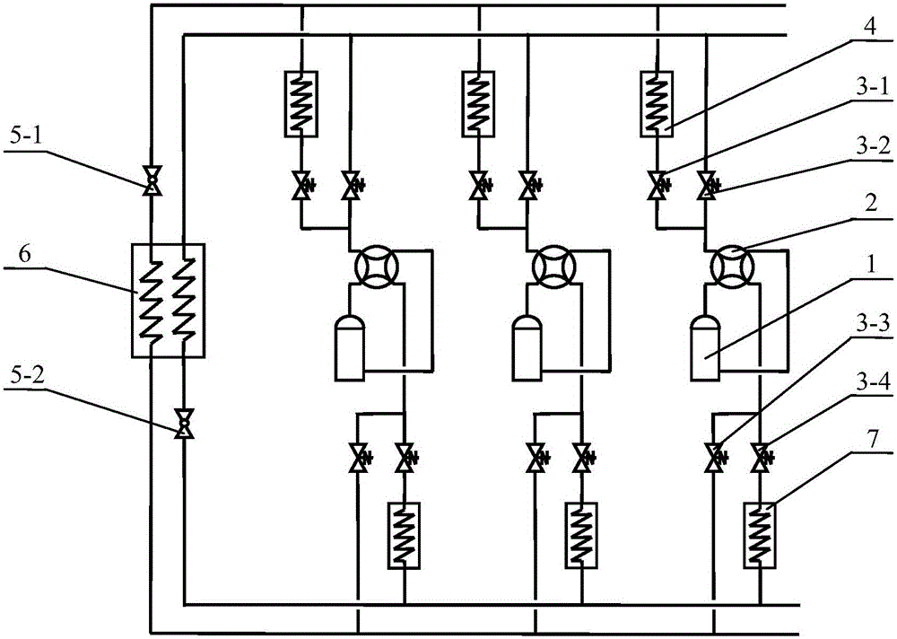
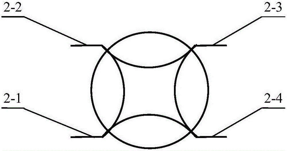
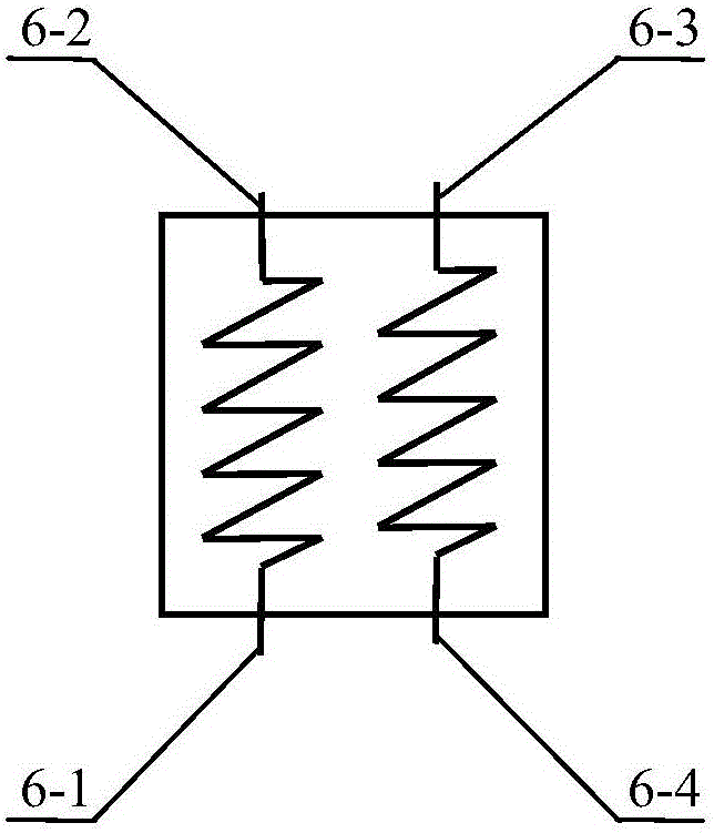
[0024] figure 1 It is a schematic diagram of a cascaded heat pump system with a variable flow single working medium in parallel connection of the first heat exchanger and the second heat exchanger of the present invention, including multiple sets of compressor units connected in parallel, a condensing evaporator 6, a first throttle valve 5-1 and The second throttle valve 5-2, each group of compressors includes a compressor 1, a four-way reversing valve 2, a first solenoid valve 3-1, a second solenoid valve 3-2, a third solenoid valve 3-3, and a second solenoid valve 3-3. Four solenoid valves 3-4, the first heat exchanger 4, and the second heat exchanger 7, the exhaust end of the compressor 1 is connected to the first interface 2-1 of the four-way reversing valve, and the compressor suction connected to the third port 2-3 of the four-way reversing valve, and the first solenoid valve 3-1 is connected in parallel with the second solenoid valve 3-2 to the second port of the four-w...


PUM


Abstract

The invention discloses a variable-flow single-working medium cascade heat pump system with parallel heat exchangers. According to the invention, each compressor unit comprises a compressor, a four-way reversing valve, four electromagnetic valves, a first heat exchanger and a second heat exchanger, wherein an exhaust end of each compressor is connected with the first connector of the corresponding four-way reversing valve; a suction end of each compressor is connected with the third connector of the corresponding four-way reversing valve; one end of each first electromagnetic valve is connected with one end of the corresponding second electromagnetic valve in parallel and then is connected with the second connector of the corresponding four-way reversing valve; the other ends of the first electromagnetic valves pass through the first heat exchangers, then are connected in parallel, and are connected with the second connector of a condensation evaporator through a first throttle valve; the other ends of the second electromagnetic valves are connected in parallel and then are connected with the third connector of the condensation evaporator; one ends of the third electromagnetic valve and the fourth electromagnetic valve are connected in parallel and then are connected with the fourth connector of the four-way reversing valve; the other ends of the third electromagnetic valves are connected in parallel and then are connected with the first connector of the condensation evaporator; the other ends of the fourth electromagnetic valves are connected in parallel and then are connected with the fourth connector of the condensation evaporator through the second heat exchangers and a second throttle valve. The cascade heat pump system of the invention is formed by single working medium, and does not contain an expansion container and other devices, so that the structure is simple.

Description

technical field [0001] The invention relates to a heat pump unit, more specifically, to a multi-head cascade heat pump cycle system, which is used to improve the efficiency of the cascade heat pump system and to regulate the flow rate of the heat pump system. Background technique [0002] The single-stage compression heat pump system is not suitable for heat pump systems with a compression ratio (ratio of exhaust pressure to suction pressure) greater than 12 due to the limitation of the suction and discharge compression ratio of the compressor. In the prior art, when the compression ratio is greater than 12, a two-stage compression heat pump system is usually used. The two-stage compression heat pump unit can be driven by a motor, or it can be realized by combining multiple heads. However, the high and low pressure of these two methods are interoperable, and the oil return problem of the compressor is not easy to solve. [0003] Cascade heat pump systems are also a good so...

Claims


Application Information

Patent Timeline
Patent Type & Authority Applications(China)
IPC IPC(8): F25B7/00F25B41/04F25B41/20
CPCF25B7/00F25B2600/25F25B41/20
Inventor 杨永安陆佩强栗琼琼贺锦开
Owner 河北航研制冷设备有限公司
Why Eureka
Eureka Blog
Learn More