
An Improved Electroplating Device for Zinc Alloy Zipper

An electroplating device and technology of zinc alloy, applied in the direction of electrodes, electrolysis components, electrolysis process, etc., can solve the problems of rough zipper elements, uneven zipper plating, scratched elements, etc., and achieve the effect of uniform coating

Inactive Publication Date: 2017-07-28
陈远婷
View PDF8 Cites 0 Cited by
  • Summary
  • Abstract
  • Description
  • Claims
  • Application Information

AI Technical Summary

Problems solved by technology

[0005] Yet adopt this improved zinc alloy zipper electroplating device to exist two problems during electroplating: 1, because the zinc alloy zipper shuttles in each cathode copper row, chain teeth can produce excessive friction with cathode copper row during electroplating, The chain teeth of the zipper are rough or even scratched. In order to overcome the defect that the plating layer of the zipper is not uniform during electroplating, in the zipper industry, it is also used to cut the zipper into sections and hang it on the corresponding hanger for hanging plating. However The production efficiency of rack plating is low

Method used


Image

  • An Improved Electroplating Device for Zinc Alloy Zipper
  • An Improved Electroplating Device for Zinc Alloy Zipper
  • An Improved Electroplating Device for Zinc Alloy Zipper

Examples


Embodiment Construction

[0042] In order to further explain the technical solution of the present invention, it will be described in detail below in conjunction with the accompanying drawings.

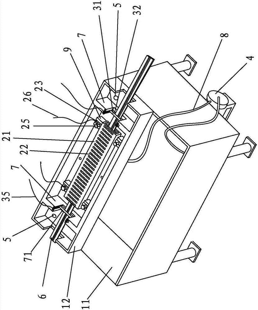
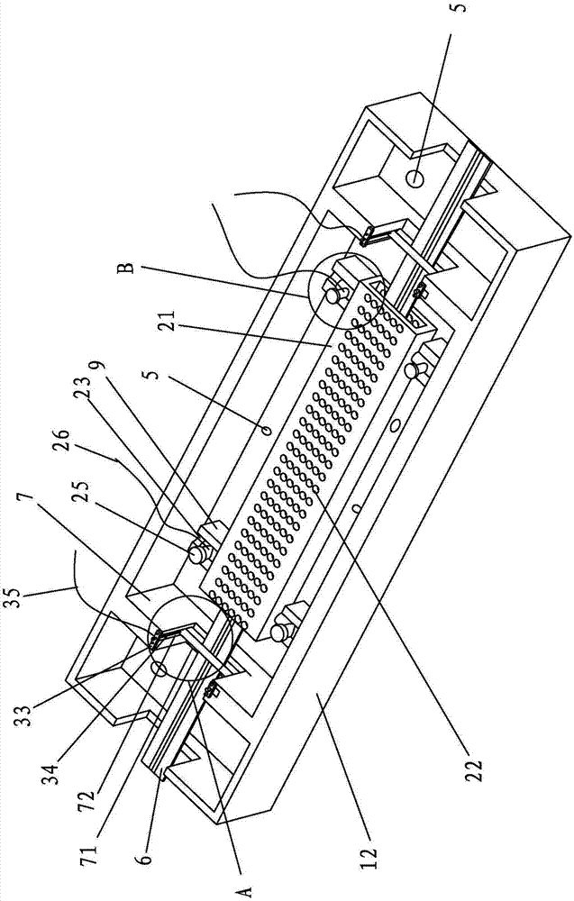
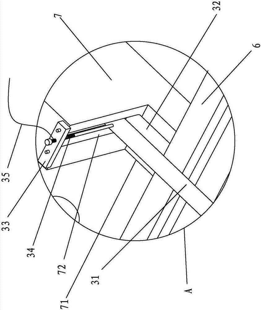
[0043] refer to Figure 1 to Figure 8 As shown, an improved zinc alloy zipper electroplating device includes a plating tank, an anode device, a cathode device in electrical contact with the zipper, and a zipper transmission device that drives the zipper 6 to move along the length of the plating tank. The plating tank consists of a liquid storage tank 11 and an electroplating tank 12 located above the liquid storage tank 11. The liquid storage tank 11 is used for placing electroplating solutions and adding electroplating chemicals. The bottom of the electroplating tank 12 is provided with a perforation (not shown), the perforation is arranged below the anode plate, and a conduit 8 is arranged between the perforation and the output port of the circulation pump. The bottom of the electroplating tank 12 is also p...


PUM


Abstract

The invention relates to an improved zinc alloy zipper electroplating device and belongs to the field of zipper electroplating devices.The improved zinc alloy zipper electroplating device comprises a plating tank, an anode device, a cathode device electrically in contact with a zipper and a zipper driving device for driving a zipper to move in the length direction of the plating tank, wherein the anode device comprises an anode plate, the anode plate is provided with a channel formed in the length direction of the anode plate, and the zipper penetrates through along the central axis of the channel.After the technical scheme is adopted, the zipper penetrates through the channel formed in the anode plate, zipper teeth on the zipper are electroplated when the zipper passes through the channel formed in the anode plate, the zipper teeth of the zipper in the channel do not produce friction with other devices in the electroplating process, and zipper tooth abrasion is not caused.The zipper located outside the channel cannot reach the deposition potential due to the fact that the current density is very small, so that a plating layer does not deposit basically.In addition, the zipper penetrates through along the central axis of the channel, the zipper teeth located in the channel are basically consistent in current density during electroplating, and it can be ensured that the plating layer is uniform during electroplating.

Description

[0001] This case is a divisional application of the Chinese invention patent application with the application number "2014101492272" and the name "A Zinc Alloy Zipper Electroplating Device". The filing date of the parent case is 2014.4.12. technical field [0002] The invention belongs to the field of zipper electroplating equipment, in particular to an improved zinc alloy zipper electroplating device. Background technique [0003] A common zinc alloy zipper, such as the Chinese Patent No.: ZL 200820145408.8 "Improved structure of a zinc alloy die-casting zipper", which includes elements, sliders, two chain straps, and the opposite sides of the two chain straps A row of chain teeth is embedded respectively, and the two rows of chain teeth are misplaced and meshed with each other. The slider is stuck on the chain teeth of the opposite side plates of the chain belt, wherein the opposite sides of the chain teeth on each of the chain belts are provided with conductive wires. The...

Claims


Application Information

Patent Timeline
Patent Type & Authority Patents(China)
IPC IPC(8): C25D7/02C25D17/12C25D17/00
CPCC25D7/02C25D17/00C25D17/12
Inventor 陈远婷
Owner 陈远婷
Learn More