Electric rotary machine

A technology of electric rotation and rotating shafts, which is applied in the manufacture of motor generators, electric components, synchronous motors for single-phase current, etc., and can solve problems such as difficulty in adopting special structures

Active Publication Date: 2016-07-06
SUZUKI MOTOR CORP
View PDF4 Cites 3 Cited by
  • Summary
  • Abstract
  • Description
  • Claims
  • Application Information

AI Technical Summary

Problems solved by technology

[0003] According to this rotor structure rotating inside the stator, the structure around which the field coil is wound is made by laminating electromagnetic steel sheets, so it is difficult to adopt a special structure

Method used


Image

  • Electric rotary machine
  • Electric rotary machine
  • Electric rotary machine

Examples


Embodiment Construction

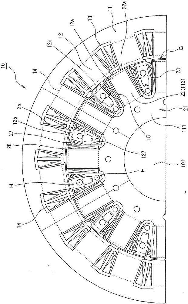
[0027] Hereinafter, embodiments of the present invention will be described in detail with reference to the drawings. Figure 1 to Figure 10 It is a figure for demonstrating an example of the reluctance motor which is one embodiment of the electric rotating machine of this invention. figure 1 It is a radial cross-sectional view of a reluctance motor, showing that the mechanical angle around the shaft center is 180 degrees, and the same structures are juxtaposed in the circumferential direction to make a reluctance motor.

[0028] As described later, figure 1 The shown reluctance motor (electric rotating machine) 10 has a structure that does not require energy input to the rotor 21 from the outside, and is suitable for mounting in, for example, a hybrid vehicle or an electric vehicle.

[0029] (Basic structure of the reluctance motor 10)

[0030] The reluctance motor 10 is provided with: a stator 11 formed in a substantially cylindrical shape; and a rotor 21 housed in the st...


PUM


Abstract

The present invention is a reluctance motor (10) that rotates as a result of the magnetic flux generated at the drive coil (14) of a stator (11) being interlinked with the rotor teeth (22) of a rotor (21). In the rotor, the key protrusion (119) of a rotor base material section (111) and the key protrusion (129) of a ring-shaped section (121) are fitted/affixed to a key groove (109) of a shaft (101), a core material section (112) that is integral to the rotor base material section is caused to be the rotor teeth provided with an electromagnet pole coil (28), the core material (25) is protected by a protruding piece (123) integral to the ring-shaped section, resulting in an inductor pole coil (27). By means of arranging in the direction of rotation in such an easy structure, it is possible to generate an induced current using the induction pole coil by means of the spatial harmonic component of the interlinked magnetic flux, and by supplying the result to the electromagnet pole coil as field magnet current, electromagnetic force is generated that assists in primary rotational force.

Description

technical field [0001] The present invention relates to an electric rotating machine, and more particularly, to an electric rotating machine having a structure in which a rotor is accommodated in a stator and the rotor is rotatable. Background technique [0002] As described in Japanese Unexamined Patent Publication No. 11-69675 (Patent Document 1), there is a type of electric rotating machine in which a rotor is accommodated in a stator and the rotor is freely rotatable, and a core material is fixed to a rotating shaft located on the rotor. The core material and the above-mentioned main shaft are prevented from rotating relative to each other, and an exciting coil for generating a rotational force is wound on the core material. [0003] According to such a rotor structure rotating inside the stator, the structure around which the field coil is wound is produced by laminating electromagnetic steel sheets, and it is difficult to adopt a special structure. [0004] prior art...

Claims


Application Information

Patent Timeline
Patent Type & Authority Applications(China)
IPC IPC(8): H02K19/10
CPCH02K3/522H02K1/148H02K3/325H02K15/022H02K15/066H02K19/103
Inventor 青山真大
Owner SUZUKI MOTOR CORP
Why Eureka
Try Eureka