Antenna tuning method and device
An antenna tuning and tuning network technology, applied in the field of communication, can solve problems such as excessive standing waves, inability to tune antennas, and real-time changes
- Summary
- Abstract
- Description
- Claims
- Application Information
AI Technical Summary
Problems solved by technology
Method used
Image
Examples
Embodiment 1
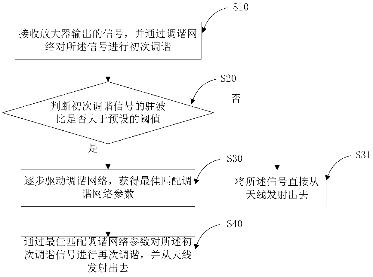
[0083] Such as image 3 As shown, the first embodiment of the present invention proposes an antenna tuning method, the method includes steps:
[0084] S10. Receive a signal output by the amplifier, and perform initial tuning on the signal through a tuning network;
[0085] S20. Determine whether the standing wave ratio of the initial tuning signal is greater than a preset threshold;
[0086] S30. If so, gradually drive the tuning network to obtain the best matching tuning network parameters; otherwise, enter step S31 and directly transmit the signal from the antenna;
[0087] S40. Perform retuning on the primary tuning signal by best matching the tuning network parameters, and transmit it from the antenna.
[0088] In this embodiment, the standing wave is intelligently detected and the tuning network is optimally matched, so that the standing wave ratio is smaller and more energy is radiated through the antenna.
[0089] In this embodiment, the signal to be sent is first am...
Embodiment 2
[0092] Such as Figure 4 As shown, in this embodiment, step S20 includes:
[0093] S21. Perform standing wave detection on the initial tuning signal in real time or at regular intervals;
[0094] S22. Calculate the standing wave ratio of the standing wave through the CPU operation unit;
[0095] S23. Compare the standing wave ratio with a preset threshold.
[0096] In this embodiment, the calculation of the standing wave ratio of the standing wave by the CPU operation unit includes:
[0097] coupling a reflected power coupling signal and an incident power coupling signal from the initial tuning signal through a bidirectional coupler;
[0098] Collect the reflected voltage value of the reflected power coupling signal through the first detection circuit connected in sequence, the first low-pass filter and the first DC acquisition module; through the second detection circuit connected in sequence, the second low-pass filter and the second The DC acquisition module acquires th...
Embodiment 3
[0101] Such as Figure 5 As shown, the present invention further provides an antenna tuning circuit, including:
[0102] Amplifier PA, used to amplify the input signal and output it to the tuning network to be tuned into the initial tuning signal;
[0103] A detection circuit for judging whether the standing wave ratio of the initial tuning signal is greater than a preset threshold; if so, gradually driving the tuning network to obtain the best matching tuning network parameters;
[0104] The tuning network is used to perform initial tuning on the signal output by the amplifier, and re-tune the initial tuning signal by best matching the parameters of the tuning network.
[0105] In this embodiment, the detection circuit includes: a bidirectional coupler, a first detection circuit connected in sequence, a first low-pass filter LPF1 and a first DC acquisition module AD1, a second detection circuit connected in sequence, a second Low-pass filter LPF2 and second DC acquisition m...
PUM
 Abstract
Description
Claims
Application Information
 - R&D
- Intellectual Property
- Life Sciences
- Materials
- Tech Scout
- Unparalleled Data Quality
- Higher Quality Content
- 60% Fewer Hallucinations
Browse by: Latest US Patents, China's latest patents, Technical Efficacy Thesaurus, Application Domain, Technology Topic, Popular Technical Reports.
© 2025 PatSnap. All rights reserved.Legal|Privacy policy|Modern Slavery Act Transparency Statement|Sitemap|About US| Contact US: help@patsnap.com


