Eureka AIR delivers breakthrough ideas for toughest innovation challenges, trusted by R&D personnel around the world.

Antenna and communication device

A technology for communication equipment and antennas, applied in antennas, resonant antennas, electrical short antennas, etc., can solve the problem of narrow bandwidth of antenna 800

Active Publication Date: 2014-12-10
HUAWEI TECH CO LTD
View PDF4 Cites 7 Cited by
  • Summary
  • Abstract
  • Description
  • Claims
  • Application Information

AI Technical Summary

Problems solved by technology

[0004] However, due to the direct connection between the above-mentioned coaxial line 83 and the radiation sheet 81, and the inner conductor substantially perpendicular to the radiation sheet 81 and the reference ground 82 presents a large inductive feature in the circuit, so that the antenna 800 narrower bandwidth

Method used


Image

  • Antenna and communication device
  • Antenna and communication device
  • Antenna and communication device

Examples


Embodiment 1

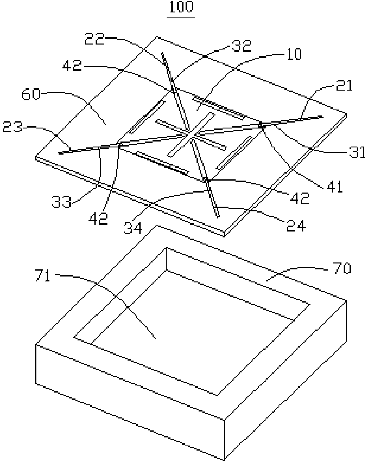
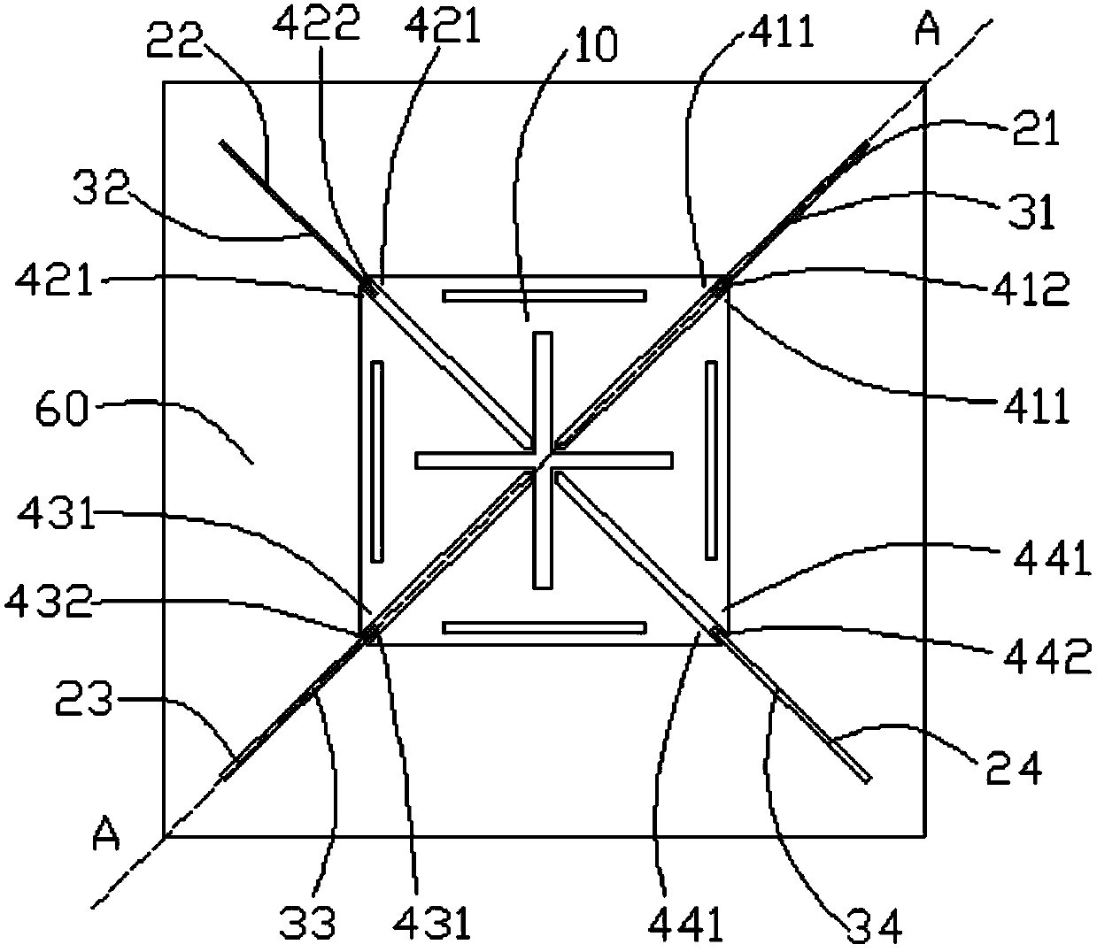
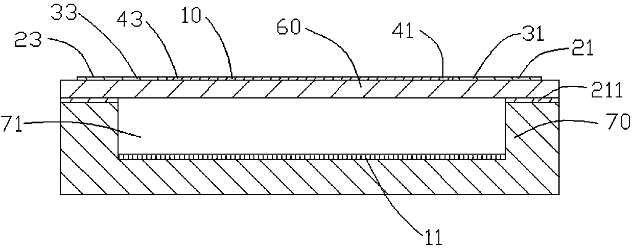
[0064] Such as figure 1 As shown, it is a schematic diagram of the exploded structure of the antenna 100 in the first preferred embodiment of the present application. The antenna 100 includes a radiation piece 10, a radiation piece reference ground 11, a first transmission line 21, a second transmission line 22, a third transmission line 23, a fourth transmission line 24, a transmission line reference ground 211, a first connection part 31, and a second connection part 32 . The third connection part 33 , the fourth connection part 34 , the first power feeding part 41 , the second power feeding part 42 , the third power feeding part 43 and the fourth power feeding part 44 .

[0065] The radiating sheet 10 is used to transmit and receive radio frequency signals. The radiating sheet 10 can be specifically a copper sheet, or a copper foil attached to a board. The shape of the radiating sheet 10 can be set as required, such as being set as The symmetrical shape can also be set as...

Embodiment 2

[0104] Based on the same inventive concept, the present application also provides a communication device, such as Figure 14 As shown, the communication device 300 includes the antenna 100 in Embodiment 1 and the transceiver 200 for receiving signals from the antenna 100 or sending signals to the antenna 100 .

[0105] The above-mentioned communication device sets the first connecting part 31 opposite to the reference ground 11 of the radiating sheet, two first radiation feeding parts 411 located in a plane, and the first transmission line feeding part 412, based on inductive The characteristic strength is proportional to the distance, and the capacitive characteristic strength is inversely proportional to the distance. Since the distance between the first connecting part 31 and the reference ground 11 of the radiation sheet is greater than the distance between the first transmission line feeding part 412 and the The distance between the two first radiation feeding parts 411, ...


PUM


Abstract

The invention discloses an antenna and a communication device. The antenna comprises a radiation sheet used for sending and receiving a radiofrequency signal, a radiation sheet reference ground oppositely arranged with the radiation sheet, a first transmission line used for transmitting the radiofrequency signal, a transmission line reference ground oppositely arranged with the first transmission line, a first connection portion connected with the first transmission line and oppositely arranged with the radiation sheet reference ground, and a first feed portion comprising a first transmission line feed portion and two first radiation feed portions, wherein the two first radiation feed portions are connected with the radiation sheet, and used for receiving the radiofrequency signal of the radiation sheet or transferring the radiofrequency signal to the radiation sheet; the first transmission line feed portion is connected with the first transmission line through the first connection portion, so as to mutually transmit the radiofrequency signal with the first transmission line; mutual coupled feed is carried out between the two first radiation feed portions and the first transmission line feed portion.

Description

technical field [0001] The invention relates to the technical field of mobile communication, in particular to an antenna and a communication device. Background technique [0002] The mobile communication system is a combination of wired and wireless, and in the mobile communication system, the transmission and reception of space wireless signals are realized by mobile antennas. It can be seen that the antenna plays an important role for the mobile communication network. [0003] Such as Figure 15 Shown is a schematic cross-sectional view of an antenna 800 in the prior art. The antenna 800 includes a radiation sheet 81 , a reference ground 82 opposite to the radiation sheet 81 , a coaxial line 83 and a circuit board 84 arranged between the radiation sheet 81 and the reference ground 82 . The outer conductor of the coaxial line 83 is welded to the reference ground 82 , the inner conductor of the coaxial line 83 passes through the circuit board 84 and is welded to the radiat...

Claims


Application Information

Patent Timeline
Patent Type & Authority Applications(China)
IPC IPC(8): H01Q1/50H01Q1/48H01Q1/38
CPCH01Q9/0457H01Q21/24H01Q1/24H01Q1/48H01Q9/0407
Inventor 罗兵石中立覃雯斐
Owner HUAWEI TECH CO LTD
Why Eureka
Eureka Blog
Learn More