
A display panel and a display device

A technology for display panels and non-display areas, applied to identification devices, magnetic objects, instruments, etc., can solve the problems of large thickness of optical glue and thick display panels, and achieve the effect of ultra-thin design and reduced thickness

Active Publication Date: 2019-06-07
BOE TECH GRP CO LTD
View PDF9 Cites 0 Cited by
  • Summary
  • Abstract
  • Description
  • Claims
  • Application Information

AI Technical Summary

Problems solved by technology

[0004] A display panel and a display device provided by the embodiments of the present invention are used to solve the problem that in the display panel of the prior art, optical glue is used to apply various functional film layers such as polarizers and touch screens. This leads to the problem of thicker display panels

Method used


Image

  • A display panel and a display device
  • A display panel and a display device
  • A display panel and a display device

Examples


Embodiment Construction

[0022] The following will clearly and completely describe the technical solutions in the embodiments of the present invention with reference to the accompanying drawings in the embodiments of the present invention. Obviously, the described embodiments are only some, not all, embodiments of the present invention. Based on the embodiments of the present invention, all other embodiments obtained by persons of ordinary skill in the art without making creative efforts belong to the protection scope of the present invention.

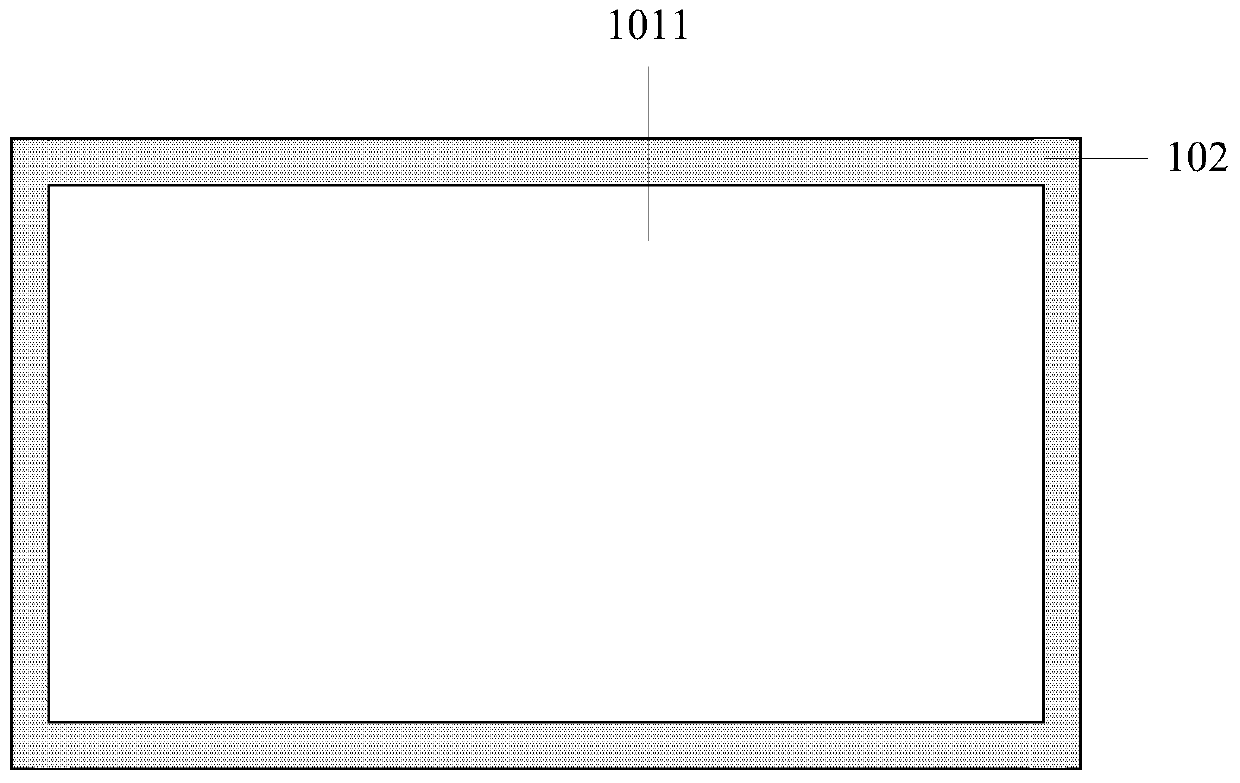
[0023] Such as figure 1 As shown, it is a schematic structural diagram of a display panel provided by an embodiment of the present invention. The display panel includes: each functional film layer 101 is stacked in sequence, and is respectively arranged on the uppermost layer 1011 and the lowermost layer 1012 of each functional film layer 101, And two film layers that can attract each other by magnetic force.

[0024] In the current display panels of the prio...


PUM

PropertyMeasurementUnit
Thicknessaaaaaaaaaa
Thicknessaaaaaaaaaa

Abstract

The invention relates to a display panel and a display device, which is used to solve the problem that the display panel in the prior art uses optical glue to paste various functional film layers such as polarizers and touch screens. For the problem of thicker, the display panel includes: each functional film layer is stacked in sequence, and two film layers are respectively arranged on the uppermost layer and the lowermost layer of each functional film layer and can attract each other through magnetic force. In the present invention, two film layers that can attract each other through magnetic force are respectively arranged on the uppermost layer and the lowermost layer of the display panel, and each film layer of the display panel is fixed by magnetic force, which replaces the optical glue in the existing display panel and reduces the cost of the display panel. The thickness further realizes the ultra-thin design of the display panel.

Description

technical field [0001] The present invention relates to the field of display panels, in particular to a display panel and a display device. Background technique [0002] With the development of display manufacturing technology, the display has been replaced by LED (Light Emitting Diode) from the original CRT (Cathode Ray Tube, light-emitting diode). Satisfied, the thinner and lighter displays are still being sought, and the popularity of ultra-thin displays is bound to become a new trend in the development of displays. In addition to the external adapter technology, monitors with thinner and lighter display panels are bound to become the first choice of users. At present, for the existing display panels, polarizers and touch screens are usually applied in the existing production process. The thickness of the optical adhesive in the existing application method is as high as 275um, resulting in a thicker display panel. Thinning requires further reduction in the thickness of ...

Claims


Application Information

Patent Timeline
IPC IPC(8): G09F9/00G09F9/33
CPCG09F9/00G09F9/33B32B3/04B32B15/04B32B15/043B32B15/18B32B2250/40B32B2250/44B32B2307/208B32B2307/546B32B2307/732B32B2457/20B32B7/025H01F1/0063H01F7/0252H01F41/16B32B7/04B32B2457/208H01F10/126H01F10/16
Inventor 杨静蔡鹏
Owner BOE TECH GRP CO LTD
Learn More