
Insertion type ultrasonic flowmeter

An ultrasonic flowmeter and plug-in technology, applied in the direction of measuring flow/mass flow, liquid/fluid solid measurement, measuring device, etc., can solve the problems of no liquid temperature detection, inconvenient maintenance and maintenance, and easy scaling on the outer surface. , to prevent inaccurate measurement, low on-site installation requirements, simple and reliable installation

Inactive Publication Date: 2016-07-06
贺成
View PDF12 Cites 2 Cited by
  • Summary
  • Abstract
  • Description
  • Claims
  • Application Information

AI Technical Summary

Problems solved by technology

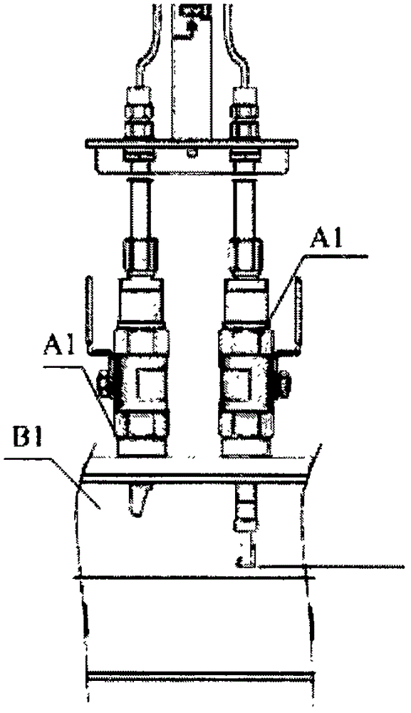
[0003] In the prior art, such as figure 1 and figure 2 As shown, after the hole is opened on site, the sensors of the two ultrasonic flowmeters A1 are installed on the pipeline B1, and the zero point adjustment and flow calibration are carried out on site. Calibration is difficult, and it makes later inspection and maintenance inconvenient
[0004] In addition, after a long time of use, the flow reflection mechanism of the existing ultrasonic flowmeter is prone to fouling on its outer surface, which affects the accuracy of flow sensing
[0005] In addition, none of the existing ultrasonic flowmeters has the function of detecting the temperature of the liquid in the pipeline

Method used


Image

  • Insertion type ultrasonic flowmeter
  • Insertion type ultrasonic flowmeter
  • Insertion type ultrasonic flowmeter

Examples


Embodiment Construction

[0039] In order to make the object, technical solution and advantages of the present invention clearer, the present invention will be further described in detail below in conjunction with the accompanying drawings.

[0040] The terms of direction and position mentioned in the present invention, such as "up", "down", "front", "back", "left", "right", "inside", "outside", "top", "bottom" ", "side", etc., are only referring to the direction or position of the drawings. Therefore, the terms used in direction and position are used to explain and understand the present invention, but not to limit the protection scope of the present invention.

[0041] Such as Figure 3 to Figure 9 As shown, it is an insertion type ultrasonic flowmeter provided in the embodiment of the present invention, which cooperates with the pipeline B2, and includes a flow reflection mechanism 1, a positioning screw 2, a ball valve 3, a pressure sensor assembly 4, a gauge assembly 14, Connecting rod 6 and tab...


PUM


Abstract

The invention provides an insertion type ultrasonic flowmeter.The insertion type ultrasonic flowmeter comprises a connecting rod; the lower end of the connecting rod is fixed to a flow reflection mechanism through a locating screw, the outer wall of the middle of the connecting rod is connected with a ball valve in a sleeved mode, and the upper end of the connecting rod is fixed to a meter head assembly through a meter head connecting assembly; a pressure sensor assembly is arranged between the ball valve and the meter head assembly and connected with the meter head assembly and a connecting pipe of the ball valve respectively; the flow reflection mechanism can be arranged in a pipeline and comprises a fixed base like a hollow pipe, the outer wall of the fixed base is fixed to the lower end of the connecting rod, two ultrasonic sensors are fixed to the upper end of the inner wall of the fixed base, and two ultrasonic reflectors are fixed to the lower end of the inner wall of the fixed base; the two ultrasonic sensors and the two ultrasonic reflectors are located in the same right-angle quadrangle, and opposite end faces of the two ultrasonic reflectors are each provided with a bevel used for reflecting ultrasonic waves.Through the insertion type ultrasonic flowmeter, installation is simple and reliable, there is no need to conduct null point debugging or flow calibration on site, and overhaul and maintenance in a later period are both convenient.

Description

technical field [0001] The invention relates to the technical field of flow measurement, in particular to an insertion type ultrasonic flowmeter. Background technique [0002] As we all know, traditional flow meters or heat meters mostly use impeller flow sensors, which have defects such as complex structure and short service life. Once used for a long time, the measurement accuracy will gradually decrease, and because the fluid contains impurities, it is often affected Serious effects such as blockage will bring losses to the use. Therefore, the ultrasonic flowmeter replaces the traditional flowmeter or heat meter because it has no mechanical moving parts and can ensure the measurement accuracy. [0003] In the existing technology, such as figure 1 and figure 2 As shown, after the hole is opened on site, the sensors of the two ultrasonic flowmeters A1 are installed on the pipeline B1, and the zero point adjustment and flow calibration are carried out on site. Calibrati...

Claims


Application Information

Patent Timeline
IPC IPC(8): G01F1/66B05B1/06
CPCG01F1/66B05B1/06
Inventor 贺成
Owner 贺成
Learn More