
Photo-thermal weak absorption testing device and method

A technology of testing device and testing method, which is applied in measurement devices, optical testing of flaws/defects, material analysis by optical means, etc., can solve the problems of unreceived receiving surface, no longer overlapping focal spots, poor reliability, etc.

Inactive Publication Date: 2016-06-29
LASER FUSION RES CENT CHINA ACAD OF ENG PHYSICS
View PDF8 Cites 3 Cited by
  • Summary
  • Abstract
  • Description
  • Claims
  • Application Information

AI Technical Summary

Problems solved by technology

However, the test object of the existing photothermal weak absorption test equipment is an optical material or film with a uniform distribution of refractive index. If it is directly used to test optical structures such as optical fibers or optical fiber preforms with axisymmetric distribution of refractive index, it will cause pumping problems. The light and the probe light are reflected or refracted multiple times inside the above-mentioned optical structure. Since the wavelengths of the probe light and the pump light are quite different, the transmission paths may be different due to refraction and reflection inside the optical fiber, and the focal spots may no longer overlap. At this time, the results detected by the receiving device cannot reflect the real material properties of the above-mentioned optical structure, and the reliability is poor
Another equally important point is that because the detection light carrying the absorption information is refracted and reflected many times, its outgoing position will generally deviate from the receiving surface of the receiving device, and the amount of deviation will usually change with the change of the test position, so that the receiving surface The detection result is affected due to the inability to receive the complete signal spot
Therefore, it is impossible to reliably test the light and heat weak absorption performance of optical structures such as optical fibers or optical fiber preforms with axisymmetric distribution of refractive index using existing heat absorption testing equipment

Method used


Image

  • Photo-thermal weak absorption testing device and method
  • Photo-thermal weak absorption testing device and method
  • Photo-thermal weak absorption testing device and method

Examples


Embodiment Construction

[0033] The technical solutions in the embodiments of the present invention will be clearly and completely described below in conjunction with the accompanying drawings in the embodiments of the present invention. Obviously, the described embodiments are only some, not all, embodiments of the present invention. Based on the embodiments of the present invention, all other embodiments obtained by persons of ordinary skill in the art without making creative efforts belong to the protection scope of the present invention.

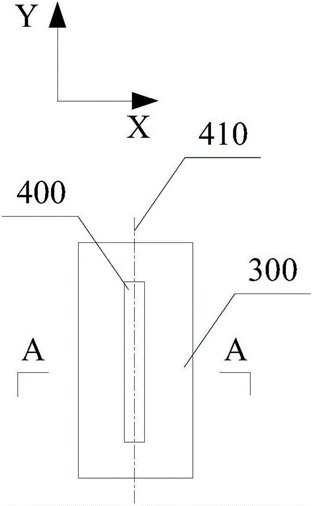
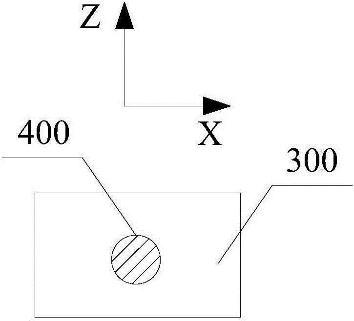
[0034] Existing photothermal weak absorption equipment for testing optical materials with uniform refractive index distribution or film layers, when used to test optical structures such as optical fibers or optical fiber preforms with axisymmetric distribution of refractive index, there will be a gap between pump light and probe light. It is difficult to overlap the focused light spots and the detection equipment cannot receive the complete signal light spots, wh...


PUM


Abstract

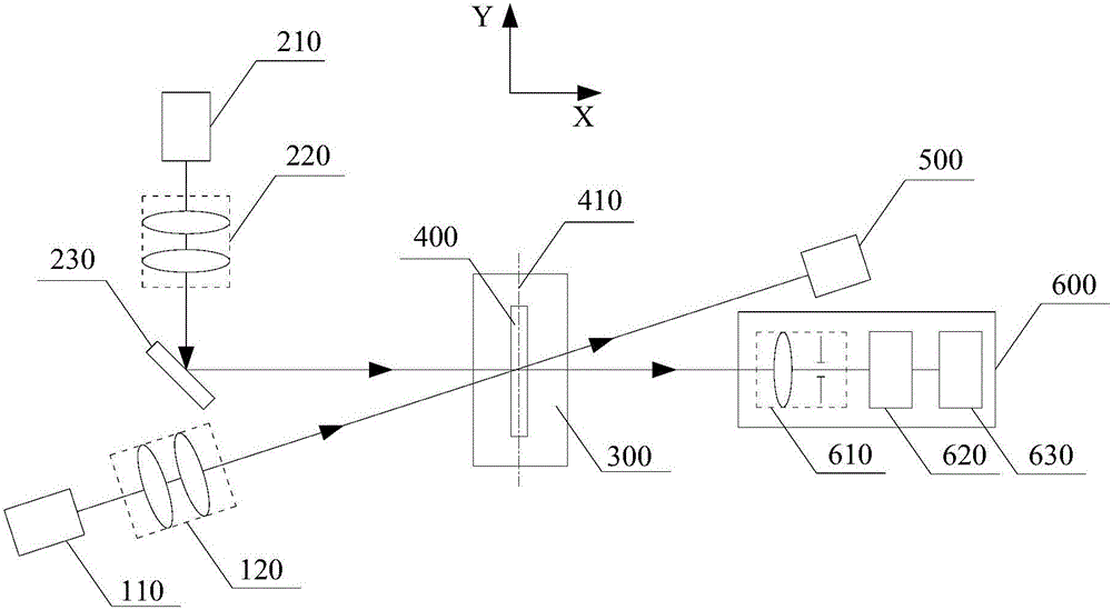
The invention provides a photothermal weak absorption testing device and method, which belong to the technical field of testing the absorptivity of optical elements. The sample is placed on the fine-tuning platform. The position of the sample to be tested is adjusted by the fine-tuning platform, so that the pump light emitted by the first light source passes through the central axis of the sample to be tested and focuses on a preset point to be measured of the sample to be tested, so that the second The probe light emitted by the light source also passes through the central axis of the sample to be measured and is focused to the preset point to be measured, and the focus spot area of ​​the probe light is larger than the focus spot area of ​​the pump light. The detection light of the sample to be measured is incident on the detector. The photothermal weak absorption test device and method provided by the embodiments of the present invention effectively realize the test of the photothermal weak absorption characteristics of an optical structure such as an optical fiber or an optical fiber preform whose refractive index is axisymmetrically distributed.

Description

technical field [0001] The invention relates to the technical field of testing the absorptivity of optical elements, in particular to a photothermal weak absorption testing device and method. Background technique [0002] Fiber lasers have many advantages such as high efficiency, good heat dissipation, high output beam quality, compact structure, and easy maintenance. They are widely used in various fields such as communications, industry, military, and medical treatment. With the expansion of application fields and the improvement of actual demand, the output power of lasers has been continuously increased. [0003] The gain medium of a fiber laser is an active fiber. The optical and material properties of the active fiber determine the output capability and performance of the fiber laser, while the fiber is obtained by pulling down a fiber preform at high temperature. The quality of the preform determines the quality of the fiber. quality. The doping uniformity of the ac...

Claims


Application Information

Patent Timeline
IPC IPC(8): G01N21/88
CPCG01N21/8806
Inventor 王凤蕊蒋晓东刘红婕周晓燕李青芝石兆华黄进耿锋叶鑫孙来喜
Owner LASER FUSION RES CENT CHINA ACAD OF ENG PHYSICS
Learn More