Heat exchanger structure

A heat exchanger and medium technology, applied in the direction of heat exchange equipment, heat exchanger type, heat exchanger shell, etc., can solve the problems of flat tube failure, heat exchanger leakage failure, etc., to eliminate thermal stress, avoid failure, The effect of preventing leakage failure

Active Publication Date: 2016-06-29
重庆超力电器有限责任公司
View PDF8 Cites 0 Cited by
  • Summary
  • Abstract
  • Description
  • Claims
  • Application Information

AI Technical Summary

Problems solved by technology

Existing heat exchangers may experience flat tube failure during use, resulting in heat exchanger leakage failure

Method used


Image

  • Heat exchanger structure
  • Heat exchanger structure
  • Heat exchanger structure

Examples


Embodiment

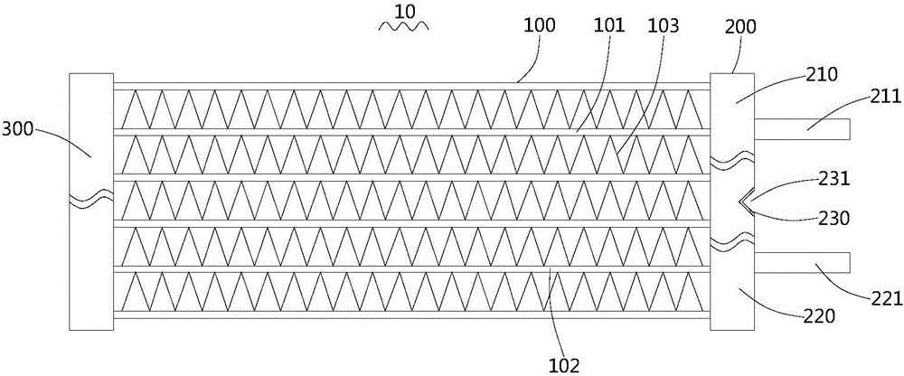
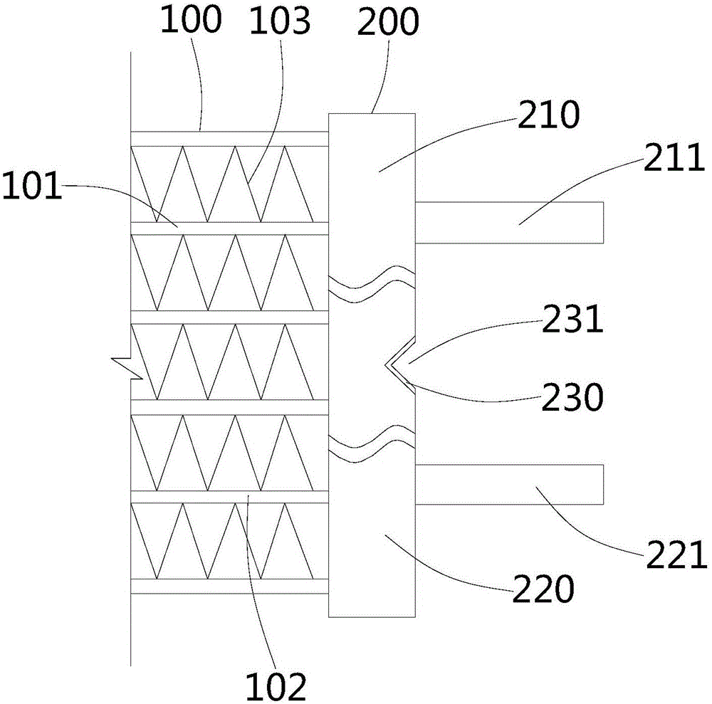
[0038] figure 1 A schematic diagram of the overall structure of the heat exchanger structure 10 provided by the embodiment of the present invention; figure 2 A schematic diagram of the local structure at the first header 200 of the heat exchanger structure 10 provided by the embodiment of the present invention; please refer to figure 1 and figure 2 , the present embodiment provides a heat exchanger structure 10 , and the heat exchanger structure 10 includes a heat exchanger body 100 , a first header 200 and a second header 300 .

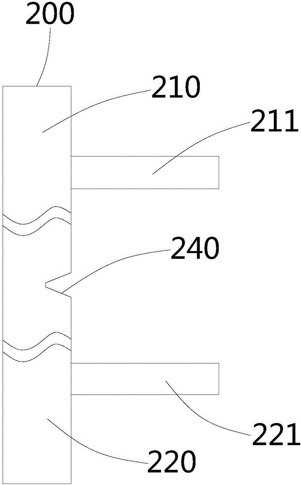
[0039] The first header 200 is provided with a medium inflow portion 210 , a medium outflow portion 220 and a separator 230 . The medium inflow part 210 is provided with an inlet 211 , and the medium outflow part 220 is provided with an outlet 221 . A plurality of first pipes 101 and a plurality of second pipes 102 are arranged on the heat exchanger body 100 . One end of the first pipe 101 communicates with the medium inflow portion 210 , and t...


PUM


Abstract

The invention provides a heat exchanger structure, and belongs to the field of heat exchange equipment. The heat exchanger structure comprises a heat exchanger body, a first header pipe and a second header pipe; the first header pipe is provided with a medium flowing-in part, a medium flowing-out part and a separating plate, an inlet is formed in the medium flowing-in part, and an outlet is formed in the medium flowing-out part; the heat exchanger body is provided with a plurality of first pipes and a plurality of second pipes, one end of each first pipe is communicated with the medium flowing-in part, the other end of each first pipe is communicated with the second header pipe, one end of each second pipe is communicated with the second header pipe, and the other end of each second pipe is communicated with the medium flowing-out part; and the medium flowing-in part and the medium flowing-out part are separated through the separating plate, and an opening is formed in one side, far away from the first header pipe, of the separating plate. By means of the heat exchanger structure, heat stress, generated by overlarge temperature differences, of the medium flowing-in part and the medium flowing-out part can be eliminated, so that the phenomenon that the first pipes and the second pipes lose efficiency due to heat stress is avoided, and leakage and efficacy losing of the heat exchanger are prevented.

Description

technical field [0001] The invention relates to the field of heat exchange equipment, in particular to a heat exchanger structure. Background technique [0002] A heat exchanger is a device that transfers part of the heat of a hot fluid to a cold fluid, also known as a heat exchanger. A heat exchanger is a device used to transfer heat from a hot fluid to a cold fluid to meet the specified process requirements. It is an industrial application of convective heat transfer and heat conduction. When the existing heat exchanger is in use, flat tube failure may occur, resulting in leakage failure of the heat exchanger. Contents of the invention [0003] The present invention provides a heat exchanger structure aimed at improving the above problems. [0004] The present invention is achieved like this: [0005] A heat exchanger structure, comprising a heat exchanger body, a first header and a second header, the first header is provided with a medium inflow part, a medium outflo...

Claims


Application Information

Patent Timeline
Patent Type & Authority Applications(China)
IPC IPC(8): F28D7/16F28F9/02F28F9/26
CPCF28D7/1692F28F9/0212F28F9/26
Inventor 吴兆智景小平马丹
Owner 重庆超力电器有限责任公司
Why Eureka
Try Eureka