High-voltage solid heat storage equipment and heat storage control method

A solid heat storage, high voltage technology, applied in heat storage equipment, lighting and heating equipment, electric heating devices, etc., can solve the problems of poor reliability, high failure rate, large leakage current, etc., to avoid high temperature damage and high measurement accuracy , the effect of improving reliability

Active Publication Date: 2019-03-19
YANTAI ZHUOYUE NEW ENERGY TECH
View PDF7 Cites 0 Cited by
  • Summary
  • Abstract
  • Description
  • Claims
  • Application Information

AI Technical Summary

Problems solved by technology

[0002] In the prior art, there are two main insulation methods for the bottom of the high-voltage power directly into the solid heat storage equipment: one is to use insulating porcelain bottles, and a carbon steel frame is added to the upper part of the insulating porcelain bottles as the load-bearing structure of the heat storage bricks, and the carbon steel structure is temperature-resistant. It is lower than 500°C, so the heat storage performance of the heat storage bricks cannot be fully exerted; the other is to use insulating bricks, but the insulation performance of the insulating bricks cannot meet the requirements, and the leakage current is large when the 10KV voltage is directly input, which has potential safety hazards. 35KV Voltage straight-in is more difficult to solve
[0003] Secondly, thermocouples are mostly used to measure the temperature of the existing high-voltage power directly into the solid heat storage body. Because the charged voltage of the heat storage body is above 10KV, the thermocouple for temperature measurement cannot directly contact the heat storage bricks, and can only measure the temperature of the air in the furnace. It cannot accurately reflect the temperature of the heat storage body itself, and cannot measure the temperature of the heating wire
[0004] Thirdly, the heating wires in the existing solid heat storage equipment are connected in series, and the entire heat storage equipment cannot operate normally after a failure occurs in one place, with high failure rate and poor reliability
[0005] On the other hand, after the solid heat storage equipment is not used for a long time, the heat storage bricks and insulating bricks are easy to be damp, and at this time, the leakage failure of the electrodes is easy to occur

Method used


Image

  • High-voltage solid heat storage equipment and heat storage control method
  • High-voltage solid heat storage equipment and heat storage control method
  • High-voltage solid heat storage equipment and heat storage control method

Examples


Embodiment Construction

[0032] The technical scheme of the present invention is described in detail below in conjunction with accompanying drawing:

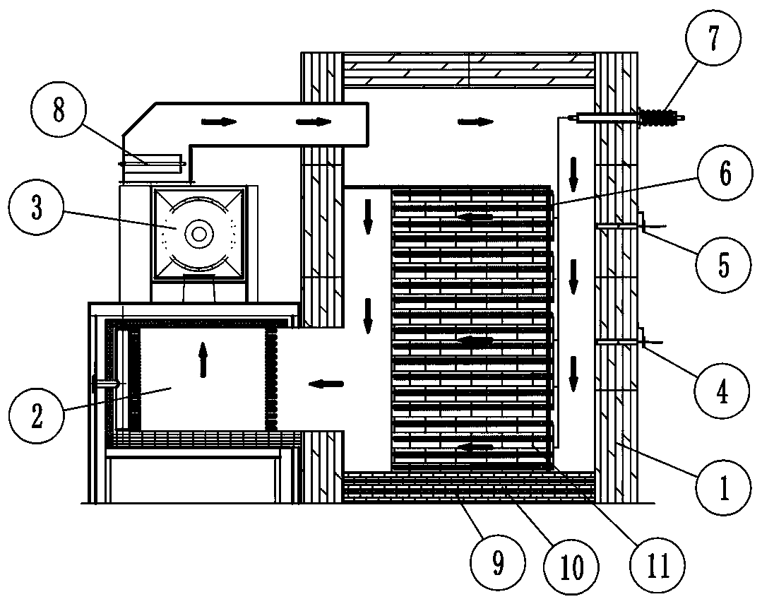
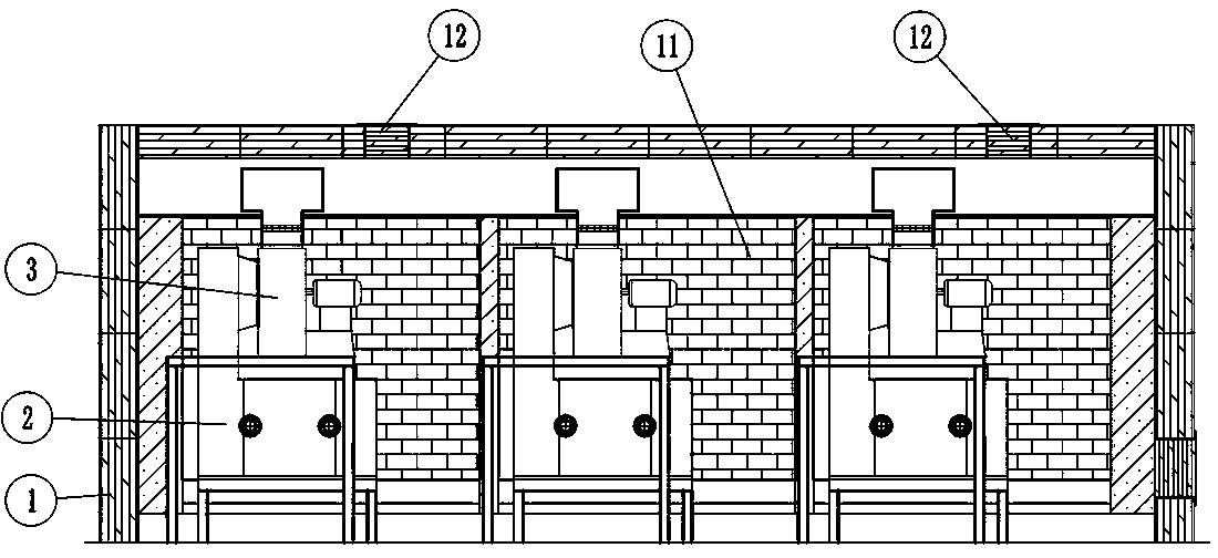
[0033] Such as figure 1 with 2 , high-voltage solid heat storage equipment, including heat storage modules and heat exchange modules;

[0034] The heat storage module includes a heat storage body composed of heat storage bricks 11, a heat insulating layer arranged on the periphery of the heat storage body, and a heating wire assembly passing through the heat storage body, and the heating wire assembly is used to heat the heat storage body; The heating wire assembly is connected with the power supply device for power supply heat storage equipment through the high-voltage ceramic joint 7;

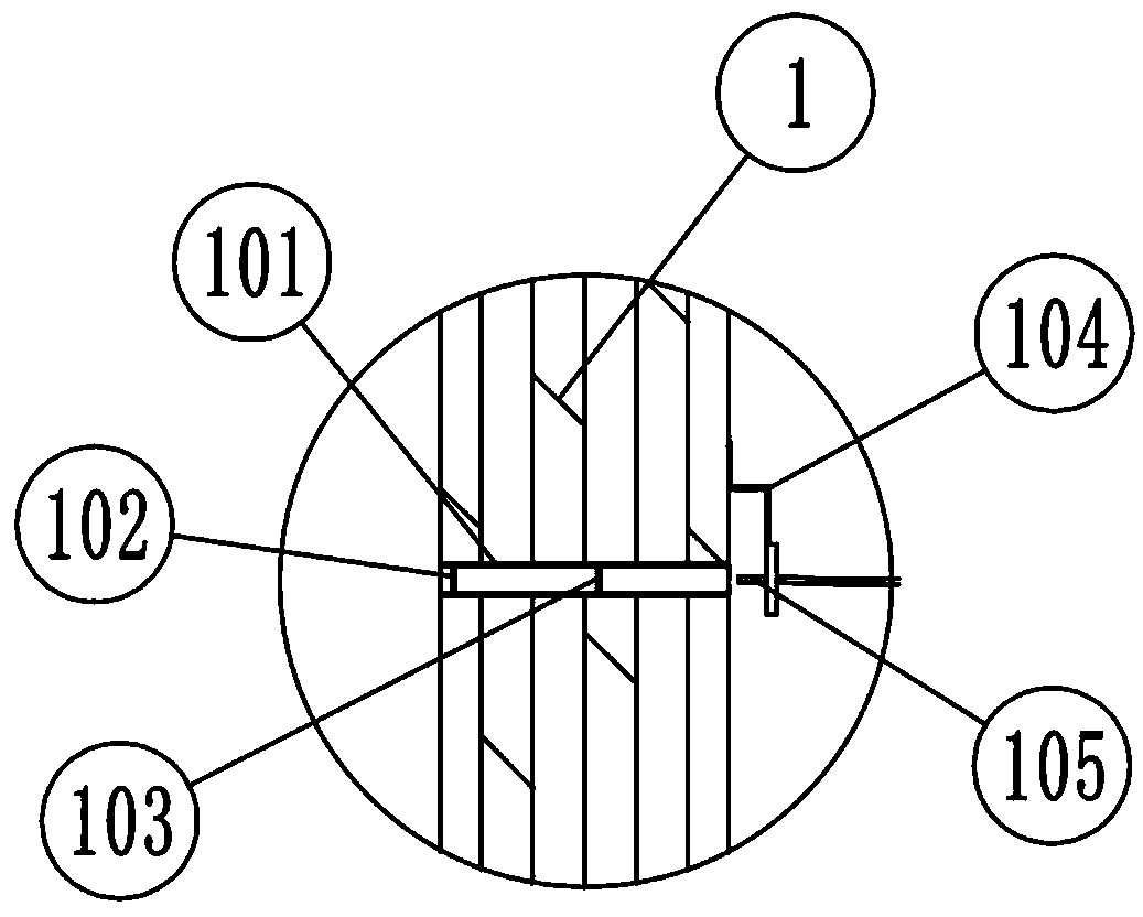
[0035] The thermal insulation layer is spliced ​​by several ceramic fiber cotton thermal insulation modules 1, which effectively solves the problems of complex external thermal insulation structure and long construction period of the heat storage body;

[0036] The ...


PUM


Abstract

The invention discloses high-voltage solid heat accumulating equipment and a heat accumulating control method. The high-voltage solid heat accumulating equipment comprises a heat accumulating module and a heat exchange module; the heat accumulating module comprises a heat accumulator consisting of heat accumulating bricks, a heat insulation layer arranged at the periphery of the heat accumulator,and a heating wire assembly penetrating through the heat accumulator; the heating wire assembly is used for heating the heat accumulator, and comprises heating wire units connected in series; each heating wire unit comprises more than four electric heating wire elements connected in parallel; and the heat accumulating module further comprises an insulation and heat preservation base. The high temperature resistance of the bottom heat insulation layer is improved, the heat accumulating properties of the heat accumulating bricks are fully exerted, precision measurement on the temperature of theheat accumulator and the temperatures of heating wires are realized, the reliability of the high-voltage solid heat accumulating equipment is improved, and the situation that the high-voltage solid heat accumulating equipment has a current leakage failure when the high-voltage solid heat accumulating equipment is not used for a long time can be avoided.

Description

technical field [0001] The invention relates to a high-voltage solid heat storage device, and also relates to a heat storage control method. Background technique [0002] In the prior art, there are two main insulation methods for the bottom of the high-voltage power directly into the solid heat storage equipment: one is to use insulating porcelain bottles, and a carbon steel frame is added to the upper part of the insulating porcelain bottles as the load-bearing structure of the heat storage bricks, and the carbon steel structure is temperature-resistant. It is lower than 500°C, so the heat storage performance of the heat storage bricks cannot be fully exerted; the other is to use insulating bricks, but the insulation performance of the insulating bricks cannot meet the requirements, and the leakage current is large when the 10KV voltage is directly input, which has potential safety hazards. 35KV Voltage straight-in is more difficult to solve. [0003] Secondly, thermocoup...

Claims


Application Information

Patent Timeline
Patent Type & Authority Patents(China)
IPC IPC(8): F28D20/00H05B3/00
CPCY02E60/14
Inventor 王真光杨子元钟克志柳光辉
Owner YANTAI ZHUOYUE NEW ENERGY TECH
Why Eureka
Try Eureka