PFC soft switch topology applied to BOOST circuit

A soft-switching and topology technology, applied in the field of switching power supply, can solve the problems of large electromagnetic interference, power density limitation, increase switching tube voltage, current stress, etc., to achieve the effect of stable operation and reduced loss

Inactive Publication Date: 2016-06-22
姚秋丽
View PDF0 Cites 3 Cited by
  • Summary
  • Abstract
  • Description
  • Claims
  • Application Information

AI Technical Summary

Problems solved by technology

In the BOOST converter, both the switch tube and the diode work in the hard switching state, which makes it difficult to further increase the switching frequency of the system, and the power density is greatly limited. Large current and voltage impact, resulting in large electromagnetic interference

Method used


Image

  • PFC soft switch topology applied to BOOST circuit
  • PFC soft switch topology applied to BOOST circuit

Examples


Embodiment Construction

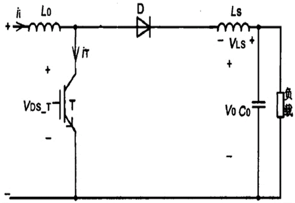
[0010] Such as figure 1 As shown, the BOOST circuit consists of an inductor ,capacitance Diode D and switch tube Composition, wherein the load is composed of resistance, adjustable. The input signal passes through the inductance transmitted to the switch tube VDS drain, The source is grounded, and the anode of diode D is connected to the switch tube The drain of the diode, the signal flows from the diode cathode output to the inductor ,capacitance Connected in parallel at both ends of the load, one end connected to the inductor , one end is grounded.

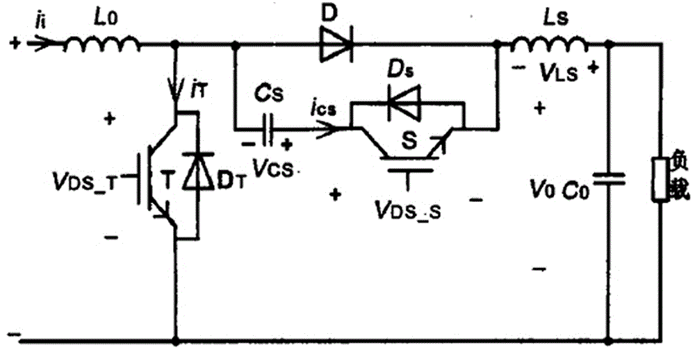
[0011] Such as figure 2 As shown, a diode is connected in parallel at both ends of the switching tube VDS , Auxiliary switch tube with diode After parallel connection with the capacitor series, and finally in parallel with the diode D as a whole, where the diode Anode connected to auxiliary switch tube The source of the diode D, which is the cathode of the diode, is then connected to the inductor ...


PUM


Abstract

The invention discloses a PFC soft switch topology applied to a BOOST circuit. According to the PFC soft switch topology, zero current shutoff of a switch tube can be realized, a topology structure of a soft tube segment of a diode can be further realized, relatively low cost, stable operation and relatively high power factor are realized, switch loss is effectively solved, and a disadvantage of a hard switch topology can be compensated.

Description

technical field [0001] The invention relates to a switching power supply, in particular to a PFC soft switching topology applied in a BOOST circuit. Background technique [0002] At present, with the grid pollution becoming more and more serious, countries around the world have formulated corresponding standards to strictly limit the equipment connected to the grid, so PFC circuits have been widely used. At present, the most simple and feasible, and also the most commonly used PFC topology is the PFC composed of BOOST converters. In the BOOST converter, both the switch tube and the diode work in the hard switching state, which makes it difficult to further increase the switching frequency of the system, and the power density is greatly limited. On the other hand, the voltage and current stress of the switch tube will be increased, and a relatively high voltage Large current and voltage shocks will generate large electromagnetic interference. Contents of the invention [...

Claims


Application Information

Patent Timeline
Patent Type & Authority Applications(China)
IPC IPC(8): H02M1/42H02M1/36
CPCY02B70/10Y02P80/10
Inventor 姚秋丽
Owner 姚秋丽
Why Eureka
Try Eureka