
Isolating and grounding switch mechanism and gas-insulated metal-enclosed switchgear

A technology for isolating grounding switches and isolating switches. It is applied in the direction of grounding switches, switchgear settings, and electric switches. It can solve the problems of large space occupation and poor durability of parts, and achieve small space occupation, reduced usage, and convenient disassembly. The effect of pretending

Active Publication Date: 2016-06-22
HENAN PINGGAO ELECTRIC +2
View PDF6 Cites 6 Cited by
  • Summary
  • Abstract
  • Description
  • Claims
  • Application Information

AI Technical Summary

Problems solved by technology

[0003] The purpose of the present invention is to provide an isolating and grounding switch mechanism to solve the problems that the current isolating and grounding switch mechanism takes up a large space in the vertical direction and the durability of parts is poor; in addition, the purpose of the present invention is to provide a Gas-insulated metal-enclosed switchgear for isolating and earthing switchgear

Method used


Image

  • Isolating and grounding switch mechanism and gas-insulated metal-enclosed switchgear
  • Isolating and grounding switch mechanism and gas-insulated metal-enclosed switchgear
  • Isolating and grounding switch mechanism and gas-insulated metal-enclosed switchgear

Examples


Embodiment Construction

[0023] Embodiments of the present invention will be further described below in conjunction with the accompanying drawings.

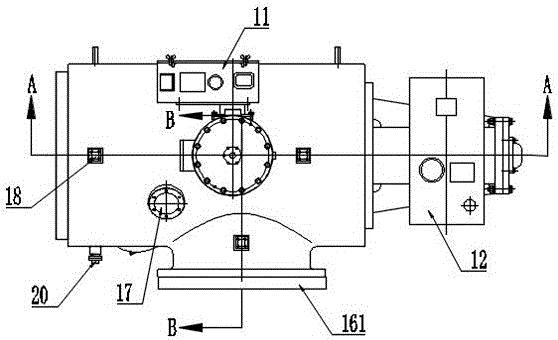
[0024] A specific embodiment of a gas-insulated metal-enclosed switchgear of the present invention, such as Figure 2 to Figure 7 As shown, the gas-insulated metal-enclosed switchgear of the present invention is a gas-insulated metal-enclosed switchgear with 3 / 2 wiring, including an isolation and grounding switch mechanism 1 , a circuit breaker 3 , a current transformer 2 and a bus bar 4 .

[0025] The isolating and grounding switch mechanism 1 includes a casing 19, a disconnector 12 assembled on the casing 19, and a grounding switch 11. The disconnector 12 includes a transmission box 121 of the disconnector mechanism, a movable contact 124 of the disconnector, a static contact 123 of the disconnector, and a grounding switch. 11 includes the transmission box 111 of the grounding switch mechanism, the moving contact 112 of the grounding switch, and the st...


PUM


Abstract

The invention relates to an isolating and grounding switch mechanism and a gas-insulated metal-enclosed switchgear. The isolating and grounding switch mechanism comprises a housing, an isolating switch and a grounding switch. The isolating switch comprises an isolating switch movable contact and an isolating switch static contact, wherein the isolating switch movable contact and the isolating switch static contact are axially arranged in parallel. The grounding switch comprises a grounding switch movable contact and a grounding switch static contact. A transformer connection terminal, an external connection terminal used for accessing a main loop to a conductive structure, a guide contact holder and a connection contact holder are arranged inside the housing, wherein the guide contact holder and the connection contact holder are horizontally arranged side by side along the axial direction. The transformer connection terminal is arranged on the guide contact holder. The isolating switch static contact is arranged on the connection contact holder and is oriented towards the guide contact holder. The external connection terminal is arranged on the connection contact holder and is used for axially accessing the main loop to the conductive structure. The isolating switch movable contact is axially guided to pass through the guide contact holder and is provided with a closing station in contact cooperation with the connection contact holder. In this way, the problem in the prior art that an existing isolating and grounding switch mechanism is large in occupation space in the vertical direction and poor in part durability can be solved.

Description

technical field [0001] The invention relates to the field of high-voltage switchgear, in particular to an isolation grounding switch mechanism and a gas-insulated metal-enclosed switchgear. Background technique [0002] At present, the current transformer connection position and the busbar connection position of the isolation grounding switch mechanism of the gas-insulated metal-enclosed switchgear with 3 / 2 connection (hereinafter referred to as GIS) are generally arranged on the left and right, such as figure 1 As shown, the isolating grounding switch mechanism 101 can only be installed in a straight line with the current transformer 102, the bus bar 104, and the circuit breaker 103 during use, which results in a long 3 / 2 wiring interval, resulting in the current 3 / 2 Wiring the problem of large GIS footprint. In order to solve the problem that GIS occupies a large area, the existing technology has used L-shaped main conductive loops to reduce the footprint of GIS electrica...

Claims


Application Information

Patent Timeline
Patent Type & Authority Applications(China)
IPC IPC(8): H01H31/00H01H31/02H02B13/075
CPCH01H31/02H02B13/075H01H31/026H01H31/003H01H31/023
Inventor 盛健薛红涛方煜瑛李健胡劲涛张皓祺彭曼秦泳黄刚
Owner HENAN PINGGAO ELECTRIC
Learn More