Sealing structure of turbo-charged direct injection engine exhaust system

A technology of exhaust system and sealing structure, applied in the direction of engine sealing, engine sealing device, engine components, etc., can solve the problems of exhaust manifold flange deformation and cracking, gasket sealing failure, bolt fracture, etc., to avoid Fracture failure, meet the sealing requirements, and avoid the effect of bolt fracture

Inactive Publication Date: 2016-06-22
CHONGQING CHANGAN AUTOMOBILE CO LTD
View PDF10 Cites 4 Cited by
  • Summary
  • Abstract
  • Description
  • Claims
  • Application Information

AI Technical Summary

Problems solved by technology

[0003] If the above-mentioned sealing structure is used in a general naturally aspirated engine, it can meet the sealing requirements; however, with the application of engine supercharging technology and in-cylinder direct injection technology, the heat load of the exhaust manifold is getting higher and higher, and the exhaust gas temperature is from 500°C rises to above 900°C. If the above-mentioned sealing structure is used in a supercharged direct injection engine, there will be the following problems: (1) The flange of the exhaust manifold is prone to large deformation and cracking under high thermal load. (2) Under the joint action of mechanical stress and large thermal stress, the exhaust manifold flange will occur along the X direction (that is, the length direction of the exhaust manifold flange, which is equivalent to figure 1 (3) Larger thermal creep of the exhaust manifold flange along the X direction will cause the gasket to slip and the sealing rib to wear, resulting in seal failure
It cannot meet the sealing requirements of supercharged direct injection engines

Method used


Image

  • Sealing structure of turbo-charged direct injection engine exhaust system
  • Sealing structure of turbo-charged direct injection engine exhaust system
  • Sealing structure of turbo-charged direct injection engine exhaust system

Examples


Embodiment Construction

[0019] The present invention will be described in detail below in conjunction with the accompanying drawings.

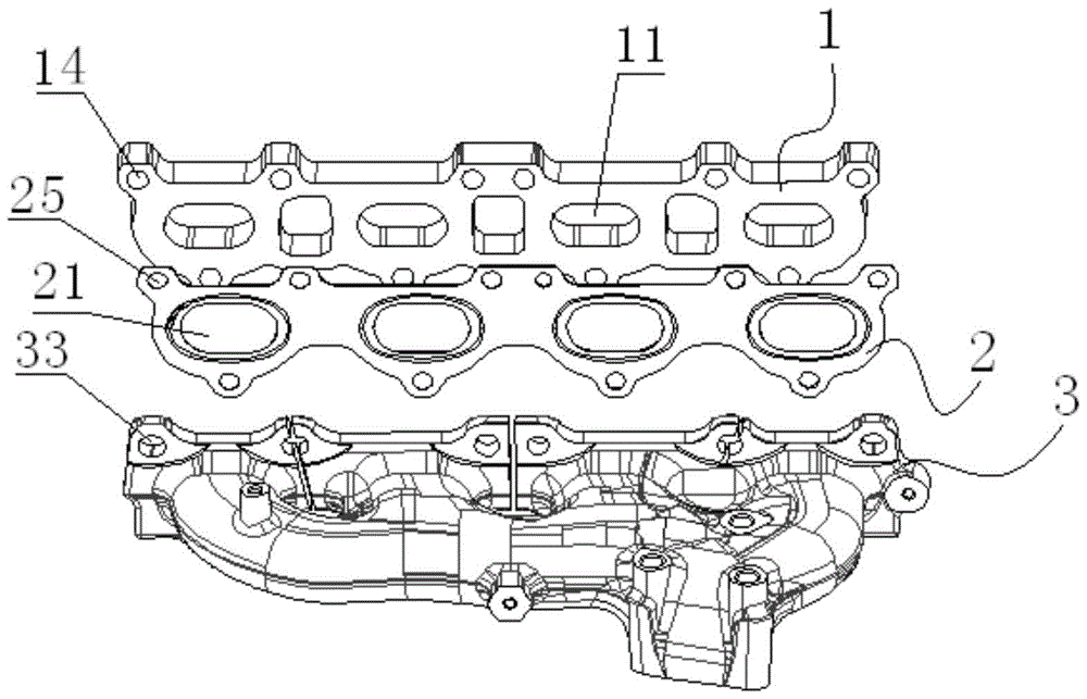
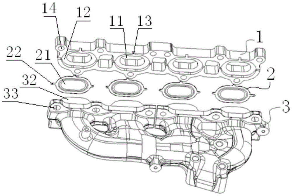
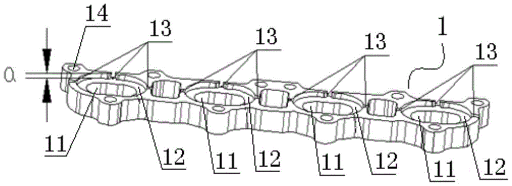
[0020] like Figure 2 to Figure 6 The sealing structure of the exhaust system of the supercharged direct injection engine shown includes a cylinder head flange 1 , four gaskets 2 and an exhaust manifold flange 3 .

[0021] like figure 2 , image 3 As shown, the edge of the cylinder head flange 1 is provided with a plurality of cylinder head bolt connection holes 14, and the cylinder head flange 1 is provided with four exhaust ports 11 (corresponding to a four-cylinder supercharged direct injection engine). Sealing grooves 12 (a total of four sealing grooves) are machined on the edges of the flange 1 corresponding to each exhaust port 11, the depth of the sealing grooves is a=5mm, and the edges of the sealing grooves 12 are provided with three limiting grooves 13. The connecting lines of the three limiting slots 13 are perpendicular to each other.

[0022] like ...


PUM


Abstract

The invention discloses a sealing structure of a turbo-charged direct injection engine exhaust system. The sealing structure comprises a cylinder head flange, sealing gaskets and an exhaust manifold flange. The cylinder head flange is provided with a plurality of exhaust outlets, the sealing gaskets are provided via holes correspondingly, and the exhaust manifold flange is provided with air duct openings as many as the exhaust outlets. Sealing grooves are formed in the edges, corresponding to the exhaust outlets, of the cylinder head flange, and the number of the sealing gaskets is equal to the number of the exhaust outlets. The sealing gaskets are matched with the end faces of the sealing grooves in shape. Exhaust pipes are arranged on the edges, corresponding to the air duct openings, of the exhaust manifold flange, the height of each exhaust pipe is equal to the depth of the corresponding sealing groove, and an inner hole of each exhaust pipe corresponds to the corresponding air duct opening. The sealing gaskets are mounted in the sealing grooves, the exhaust pipes stretch into the sealing grooves, press the sealing gaskets and are in clearance fit with the sealing grooves, the exhaust outlets, the via holes, the inner holes and the air duct openings communicate with one another correspondingly, and the cylinder head flange and the exhaust manifold flange are connected through bolts and nuts. By means of the sealing structure, the bolts can be prevented from being broken, and the sealing gaskets are protected against seal failures.

Description

technical field [0001] The invention belongs to the field of engine exhaust systems, and in particular relates to a sealing structure for the exhaust system of a supercharged direct injection engine. Background technique [0002] like figure 1 As shown, the sealing structure of the existing engine exhaust system includes a cylinder head flange 1, a gasket 2 and an exhaust manifold flange 3, and the edge of the cylinder head flange 1 is provided with a plurality of cylinder head bolt connection holes 14, There are four exhaust ports 11 on the cylinder head flange 1, and the gasket 2 is an integrated flange structure, which is composed of the upper metal corrugated substrate, the middle metal corrugated substrate and the lower metal corrugated substrate by welding, and the edge of the gasket 2 is opened. There are a plurality of gasket bolt connection holes 25 corresponding to the cylinder head bolt connection holes 14. The gasket 2 is provided with four through holes 21 corr...

Claims


Application Information

Patent Timeline
Patent Type & Authority Applications(China)
IPC IPC(8): F01N13/18F01N13/10F02F11/00F16J15/08
CPCF01N13/10F01N13/1805F01N13/1827F01N13/1844F16J15/0825F16J2015/0875
Inventor 王凤娟胡春林刘彦华王建锋余锴胡清池
Owner CHONGQING CHANGAN AUTOMOBILE CO LTD
Why Eureka
Try Eureka