Splice channel unit, splicer and textile machine

A technology of splicing channels and splicers, which is applied to spinning machines, textiles and papermaking, and continuous winding spinning machines, and can solve financial, supply and labor waste problems

Active Publication Date: 2016-06-22
SAURER GERMANY GMBH & CO KG
View PDF9 Cites 4 Cited by
  • Summary
  • Abstract
  • Description
  • Claims
  • Application Information

AI Technical Summary

Problems solved by technology

This in turn results in a great waste of finances, supplies, and labor

Method used


Image

  • Splice channel unit, splicer and textile machine
  • Splice channel unit, splicer and textile machine
  • Splice channel unit, splicer and textile machine

Examples


Embodiment Construction

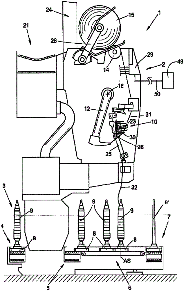
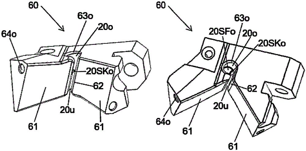
[0038] figure 1 - taken from DE 10 224 080 A1 (where the designation is also the same) - schematically shows a side view of a workstation 2 of a textile machine 1, in this case an automatic cross-winder 1 with a splicer 10, according to The splicing channel unit of the present invention can be used in the splicer. figure 2 - also taken from DE 10 224 080 A1 (also with the same designation) - a perspective view of the splicer 10 is then given.

[0039] Automatic crosswinders 1 of this type are known to have a plurality of identical workstations 2 , in the present case winding units 2 , between their end stations (not shown). At these package units, the winding bobbins 9 are rewound into bulky cross-wound packages 15 .

[0040] The package unit 2 has a splicer 10 (which is arranged slightly rearward with respect to the normal path of the yarn) to combine the so-called upper yarn 31 from the cross-wound package 15 and the yarn from the winding bobbin 9 The so-called lower yar...


PUM

PropertyMeasurementUnit
lengthaaaaaaaaaa
lengthaaaaaaaaaa

Abstract

The invention relates to a splice channel unit, a splicer and a textile machine. Here, air inlet ducts (660, 66u) are especially designed to be a splice channel (20) injecting splice air into the splice channel unit (60). According to specific variants of the splice channel unit, the splice channel unit has a) the minimum of the length l of a portion (69o, 69u) near outlets and the minimum of the diameter d of the outlets (70o, 70u) communicated with the splice channel (20), b) a value of the ratio r<ld>=l/d exceeding the minimums, wherein the portion (69o, 69u) near the outlets must basically not have structures which may prevent the splice air from flowing under the condition a) and the condition b), or c) the air inlet ducts (660, 66u) designed to enable the splice air to form a laminar flow imported to the splice channel (20) before the outlets (70o, 70u) of the splice channel (20) of the air inlet ducts when the splice air flows through the splice channel.

Description

technical field [0001] The invention relates to a splicing channel unit for an air splicer, a splicer comprising a splicing channel unit of this type and a textile machine having a splicer of this type. Background technique [0002] The term "splicer" as used herein means a device for joining the two ends of a yarn, wherein, here and hereinafter, in any case, the yarn is considered to refer to a The structure of each fiber. In an air splicer, the yarns are joined together by inserting the yarns to be joined through the feed slot into the splicing channel of the splicer, then compressed air is blown into the splicing channel through at least one inlet opening , so that the yarn fibers intermingle and twist to form a joint that has the same appearance and strength as the rest of the yarn structure. In this process, the terms "compressed air" or "splicing air" are used here to designate all suitable connecting media, which therefore include in particular moist air in addition...

Claims


Application Information

Patent Timeline
Patent Type & Authority Applications(China)
IPC IPC(8): D01H7/86D01H13/00D01H1/10D01H1/24
CPCD01H1/10D01H1/24D01H7/86D01H13/00B65H69/061B65H2701/31
Inventor O·内比格S·斯查顿
Owner SAURER GERMANY GMBH & CO KG
Why Eureka
Try Eureka