


Quick Research
Generate reliable direction feasibility study reports for your R&D in just a few steps.

Technical Q&A
Discover and master advanced knowledge NOW. Basics, ideas, possibilities, all at once.

Find Solutions
As an expert in R&D theories, this can generate solutions to your technical problems instantly.

Evaluate Feasibility
Analyze your overall solution with one click, know your potential R&D risks in advance.

Monitor Landscape
Get weekly tech updates, stay abreast of the latest tech innovations and key insights.
Optical component and timepiece
A technology for optical components and clocks, applied in optical components, clocks, optics, etc., can solve the problems of poor productivity and high production costs of optical components, and achieve the effect of simple structure
- Summary
- Abstract
- Description
- Claims
- Application Information
AI Technical Summary
Problems solved by technology
Method used
Image

Examples
no. 1 Embodiment approach
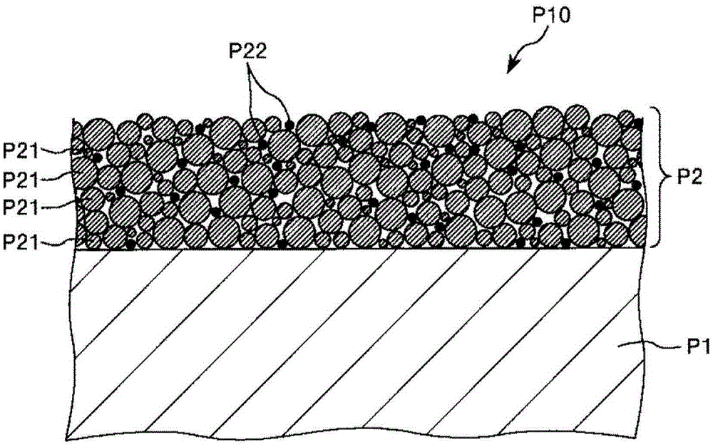
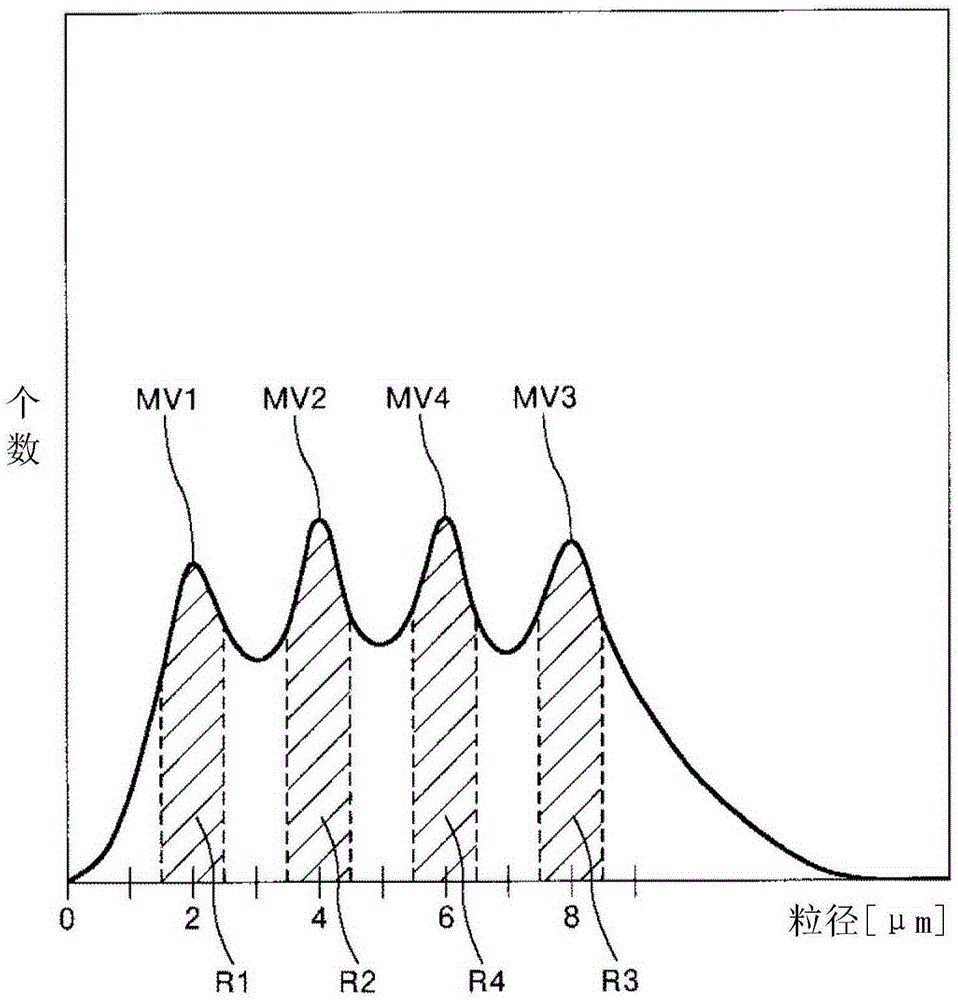
[0036] figure 1 It is a cross-sectional view schematically showing the first embodiment of the optical component of the present invention. figure 2 It is a figure which shows typically an example of the particle size distribution of the silica particle which comprises the anti-reflection film of the optical component of this invention.
[0037] Such as figure 1 As shown, the optical component P10 of this embodiment includes a base material P1 and an anti-reflection film P2 containing silica particles P21.
[0038] In addition, the silica particles P21 contained in the anti-reflection film P2 have a predetermined particle size distribution.
[0039] That is, the silica particles P21 contained in the anti-reflection film P2 have the first maximum value MV1 in the range of 1.5 nm to 2.5 nm (the first range R1) in the number-based particle size distribution, which is at 3.5 nm There is a second maximum value MV2 in the above 4.5nm range (second range R2), and a third maximum value MV3 i...
no. 2 Embodiment approach
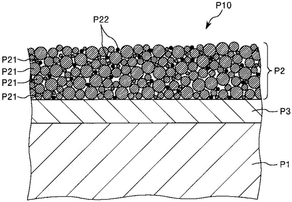
[0104] image 3 It is a cross-sectional view schematically showing the second embodiment of the optical component of the present invention. In the following description, differences from the above-mentioned embodiment will be mainly described, and description of the same matters will be omitted.
[0105] Such as image 3 As shown, the optical component P10 of this embodiment includes a substrate P1, an anti-reflection film P2 containing silica particles P21, and a base layer P3.
[0106] By having the base layer P3 in this way, for example, the close adhesion between the base material P1 and the anti-reflection film P2 (adherence via the base layer P3) can be particularly excellent, and the durability and reliability of the optical component P10 can be particularly excellent . As the constituent material of the base layer P3, for example, various resin materials, SiO 2 Wait.
[0107] The thickness of the base layer P3 is not particularly limited, but it is preferably 5 nm or more a...
Embodiment 1
[0176] The glass cover which is an optical component is manufactured by the method shown below.
[0177] First, a plate (glass plate) made of sapphire glass is prepared as a base material (base material preparation step), and necessary parts are cut and polished. The base material after cutting and grinding is approximately disc-shaped, with a size of diameter: 30 mm × thickness: 1 mm.
[0178] Next, the surface of the base material on the side where the anti-reflection film is to be formed is subjected to an ultraviolet irradiation treatment to irradiate ultraviolet rays with a wavelength of 248 nm.
[0179] Next, the composition for forming an anti-reflection film is applied to the entire one surface of the substrate by a spraying method (the composition applying step for forming an anti-reflection film).
[0180] As a composition for forming an anti-reflection film, tin oxide (SnO) which is a mixture of silica particles and conductive particles (conductive transparent metal oxide p...
PUM
| Property | Measurement | Unit |
|---|---|---|
| particle diameter | aaaaa | aaaaa |
| particle diameter | aaaaa | aaaaa |
| particle diameter | aaaaa | aaaaa |
Abstract
Description
Claims
Application Information
 - R&D Engineer
- R&D Manager
- IP Professional
- Industry Leading Data Capabilities
- Powerful AI technology
- Patent DNA Extraction
Browse by: Latest US Patents, China's latest patents, Technical Efficacy Thesaurus, Application Domain, Technology Topic, Popular Technical Reports.
© 2024 PatSnap. All rights reserved.Legal|Privacy policy|Modern Slavery Act Transparency Statement|Sitemap|About US| Contact US: help@patsnap.com