
Acoustic vector array DOA estimation method

A technology of azimuth estimation and acoustic vector array, which is applied to systems for determining direction or offset, direction finders using ultrasonic/sonic/infrasonic waves, etc. computational problems, etc.

Active Publication Date: 2016-06-15
HUAWEI TEHCHNOLOGIES CO LTD
View PDF5 Cites 25 Cited by
  • Summary
  • Abstract
  • Description
  • Claims
  • Application Information

AI Technical Summary

Problems solved by technology

The algorithm needs to perform singular value decomposition on the received data or eigenvalue decomposition on the covariance matrix. Once the number of receiving array elements is large, the amount of calculation for signal processing will also increase greatly. These are not used in hardware such as FPGA or DSP. accomplish
Proceedings of 2010 International Colloquium on Computing, Communication, Control, and Management Volume 1 "Multi-invariance MUSICA Algorithm for DOA Estimation in Acoustic Vector-sensor Array" proposes the DOA estimation of the acoustic vector sensor array under the MI-MUCIS algorithm. This algorithm makes full use of the invariance of the data structure, and the DOA estimation uses a simple Dimensional search, to a certain extent, reduces the amount of computation and improves robustness, but the algorithm still has some shortcomings: first, when processing time series signals, it does not fully consider the time structure characteristics of the signal source; second, in small Under the condition of snapshot number or low SNR, the robustness and estimation accuracy of the algorithm are not enough. Third, when there is an error in the estimation of the number of sources, the performance of the algorithm will decline to a certain extent.

Method used


Image

  • Acoustic vector array DOA estimation method
  • Acoustic vector array DOA estimation method
  • Acoustic vector array DOA estimation method

Examples


Embodiment Construction

[0079] The technical solutions of the present invention will be described in detail below in conjunction with the accompanying drawings.

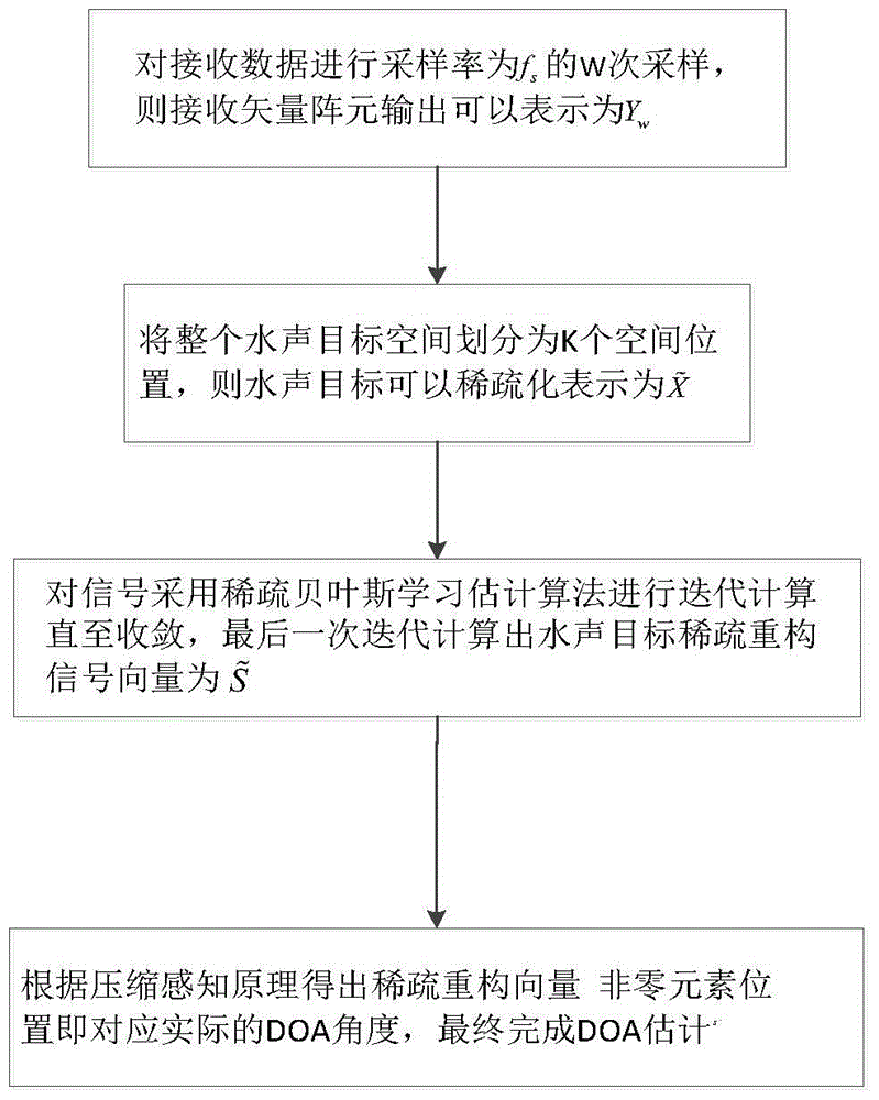
[0080] Such as figure 1 As shown, the present invention provides a method for estimating the direction of an acoustic vector array, comprising the following steps:

[0081] (1) Suppose there are L long-range underwater acoustic targets, and the L signals sent by them are narrow-band signals with frequency f, the receiving signal array is a uniform linear array containing M vector sensor elements, and the distance between the array elements is The half-wavelength of , the output of the array element is expressed in matrix form as follows:

[0082] Y=A(θ)S+N(1)

[0083] Among them, Y=[Y 1 T ,Y 2 T ,...,Y M T ] T , T represents the transpose; A(θ) represents the array popular matrix of the signal, S represents the remote underwater acoustic target signal source, S=[s 1 ,s 2 ,...s L ] T , N indicates that the additive noise o...


PUM


Abstract

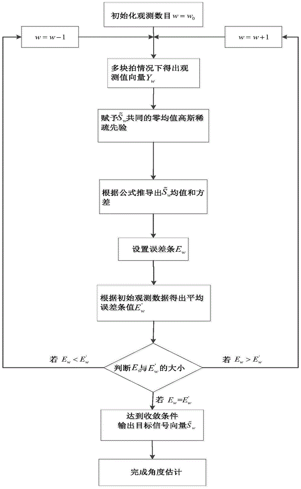
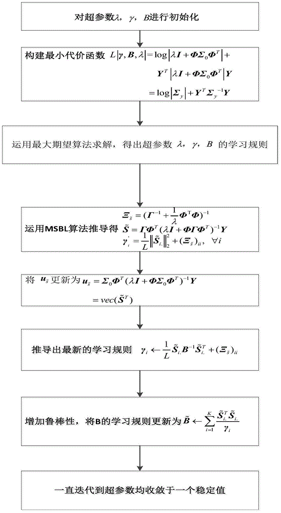
The invention discloses an acoustic vector array DOA estimation method, which comprises the steps that: signals sent by L remote underwater acoustic targets are narrowband signals at frequency f, a receiving signal array is a uniform linear array comprising M vector sensor array elements, and an array element distance is half wavelength of the transmitted signals; an entire underwater acoustic target space is divided into K spatial positions, and each spatial position corresponds to one directional angle; a sparse bayesian learning DOA estimation algorithm is adopted for the signal Sw<~>, a maximum posterior probability of a signal source is obtained to achieve azimuth angle estimation of the targets through solving a value of a hyper-parameter, the hyper-parameter is subjected to iterative calculation till convergence, and an underwater acoustic target sparse reconstructed signal vector is calculated to be Si<~> through the final iterative calculation; a position of a S<~> non-zero row is determined, a non-zero element position of the sparse reconstructed vector S<~> corresponds to an actual DOA angle, and the DOA estimation is completed finally. The acoustic vector array DOA estimation method can improve DOA estimation accuracy, obtains more incisive directional beams and lower side lobes, and achieves omnibearing DOA estimation.

Description

technical field [0001] The invention belongs to the technical field of marine engineering, and relates to a method for estimating a direction of arrival in array signal processing, in particular to a method for estimating DOA of an acoustic vector array based on multi-task Bayesian learning. Background technique [0002] Underwater acoustic target orientation estimation is an important content of underwater signal processing research, and it is also a key problem that current underwater equipment urgently needs to solve. Vector hydrophone technology is a new technology to detect the direction and intensity of sound energy flow in water. Vector hydrophone not only has frequency-independent dipole directivity, which is suitable for detection and measurement of low-frequency signals, but also is compatible with sound pressure Compared with the array composed of hydrophones, its volume and weight are much smaller under the premise of achieving the same technical indicators. The...

Claims


Application Information

Patent Timeline
Patent Type & Authority Applications(China)
IPC IPC(8): G01S3/802
CPCG01S3/802
Inventor 王彪沈小正
Owner HUAWEI TEHCHNOLOGIES CO LTD
Learn More