A heat recovery device structure and air-cooled heat pump unit

A heat recovery device and water heat exchanger technology, applied in the field of heat pumps, can solve problems such as low pressure protection, insufficient liquid supply of electronic expansion valves, refrigerant heat recovery devices cannot be taken away, etc., to achieve reliable operation, high work efficiency, and improved reliability sexual effect

Active Publication Date: 2018-11-06
QINGDAO HAIER AIR CONDITIONING ELECTRONICS CO LTD
View PDF4 Cites 0 Cited by
  • Summary
  • Abstract
  • Description
  • Claims
  • Application Information

AI Technical Summary

Problems solved by technology

[0003] However, the above-mentioned structure has the following problems: in actual use, the inlet water temperature of the water heat exchanger is not a fixed value, when the inlet water temperature is low, the refrigerant not only absorbs sensible heat, but also absorbs part of latent heat, resulting in part of the refrigerant After condensation in the water heat exchanger, it accumulates at the bottom of the heat recovery device and cannot be taken away, resulting in insufficient liquid supply at the front end of the electronic expansion valve, and low-pressure protection occurs during operation or startup, seriously affecting the normal operation of the air-cooled heat pump unit

Method used


Image

  • A heat recovery device structure and air-cooled heat pump unit
  • A heat recovery device structure and air-cooled heat pump unit
  • A heat recovery device structure and air-cooled heat pump unit

Examples


Embodiment 1

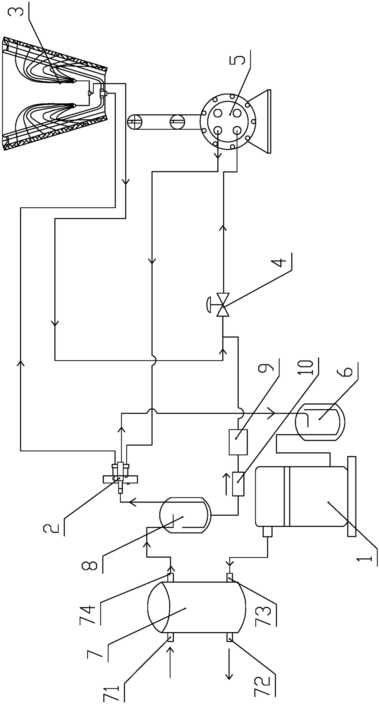
[0026] This embodiment provides a heat recovery device structure, such as figure 1 As shown, the heat pump system includes a compressor 1 , a four-way valve 2 , a condenser 3 , an electronic expansion valve 4 , an evaporator 5 and a first gas-liquid separator 6 , which are connected in sequence through pipelines. In this embodiment, the condenser 3 adopts a fin heat exchanger, and the evaporator 5 adopts a dry evaporator.

[0027] A water heat exchanger 7 is provided between the compressor 1 and the four-way valve 2. The water heat exchanger 7 has a water inlet 71, a water outlet 72, a refrigerant inlet 73 and a refrigerant outlet 74. The refrigerant inlet 73 of the water heat exchanger 7 It is connected to the compressor 1, and the refrigerant outlet 74 is connected to the four-way valve 2, so that the high-temperature and high-pressure gaseous refrigerant compressed by the compressor 1 first enters the water heat exchanger 7 for heat exchange with water, and then enters the ...

Embodiment 2

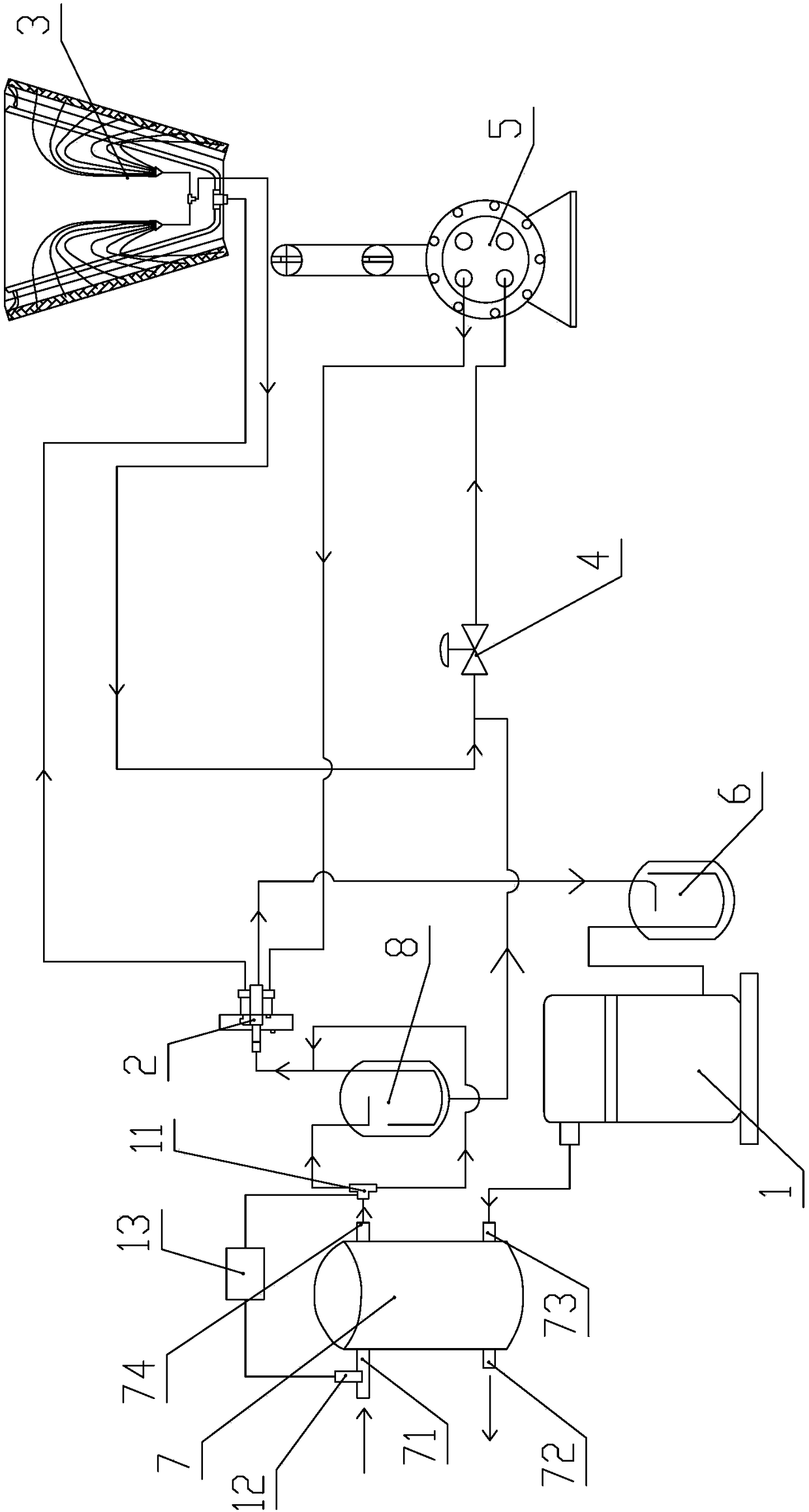
[0034] This embodiment provides a heat recovery device structure, such as figure 2 As shown in the figure, its structure is basically the same as that of the first embodiment, and its heat pump system includes a compressor 1, a four-way valve 2, a condenser 3, an electronic expansion valve 4, an evaporator 5 and a first gas-liquid separator 6 connected by pipelines in sequence. A water heat exchanger 7 is arranged between the compressor 1 and the four-way valve 2 , and a second gas-liquid separator 8 is also arranged between the water heat exchanger 7 and the four-way valve 2 .

[0035] The difference is that in this embodiment, a reversing valve 11 is provided between the water heat exchanger 7 and the second gas-liquid separator 8, and the inlet of the reversing valve 11 is connected to the refrigerant outlet 74 of the water heat exchanger 7, and the The first outlet of the valve 11 is connected to the inlet of the second gas-liquid separator 8 , and the second outlet is di...

Embodiment 3

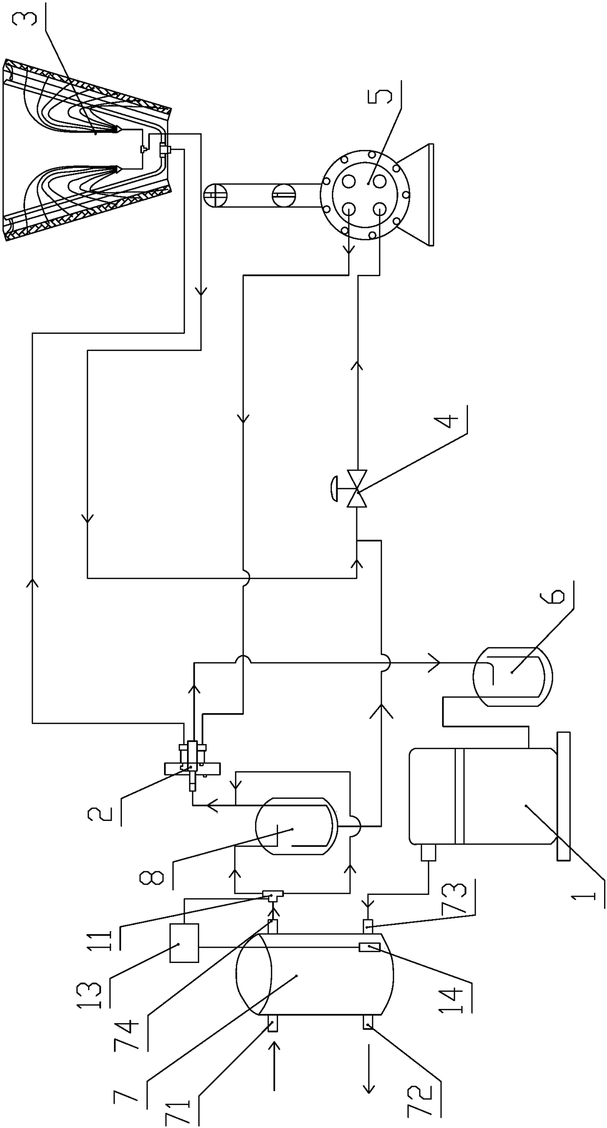
[0039] This embodiment provides a heat recovery device structure, such as image 3 As shown in the figure, its structure is basically the same as that of the first embodiment, and its heat pump system includes a compressor 1, a four-way valve 2, a condenser 3, an electronic expansion valve 4, an evaporator 5 and a first gas-liquid separator 6 connected by pipelines in sequence. A water heat exchanger 7 is arranged between the compressor 1 and the four-way valve 2 , and a second gas-liquid separator 8 is also arranged between the water heat exchanger 7 and the four-way valve 2 .

[0040] The difference is that in this embodiment, a reversing valve 11 is provided between the water heat exchanger 7 and the second gas-liquid separator 8, and the inlet of the reversing valve 11 is connected to the refrigerant outlet 74 of the water heat exchanger 7, and the The first outlet of the valve 11 is connected to the inlet of the second gas-liquid separator 8, the second outlet is directly...


PUM


Abstract

The invention discloses a heat recoverer structure and an air-cooled heat pump unit and relates to the technical field of heat pumps. The heat recoverer structure and the air-cooled heat pump unit are designed for solving the problem that the liquid feeding pressure of an electronic expansion valve is insufficient due to the fact that the water inlet temperature of a heat exchanger of an existing heat recoverer is low. The heat recoverer structure comprises a compressor, a water heat exchanger, a condenser, an electronic expansion valve, an evaporator and a first gas-liquid separator which are connected in sequence, and the water heat exchanger is used for conducting heat exchanging with water. The heat recoverer structure further comprises a second gas-liquid separator. An inlet of the second gas-liquid separator is connected with a refrigerant outlet of the water heat exchanger. An air outlet of the second gas-liquid separator is connected with the condenser. A liquid outlet of the second gas-liquid separator is connected with the front end of the electronic expansion valve. According to the heat recoverer structure provided by the invention, gas-liquid separating is conducted on refrigerant flowing out of the water heat exchanger by additionally arranging the gas-liquid separators, the separated liquid refrigerant is directly introduced to the front end of the electronic expansion valve, and even if the water inlet temperature in the water heat exchanger is low, the effect that liquid feeding of the front end of the electronic expansion valve is sufficient can also be ensured, so that the operational reliability is greatly improved.

Description

technical field [0001] The invention relates to the technical field of heat pumps, in particular to a heat recovery device structure and an air-cooled heat pump unit having the heat recovery device structure. Background technique [0002] In the existing air-cooled heat pump unit, a water heat exchanger is generally installed between the condenser and the compressor, and the sensible heat of the refrigerant flowing out of the compressor is recovered by the water heat exchanger to produce hot water, so as to effectively utilize the heat. ,Energy saving. [0003] However, the above structure has the following problems: because in actual use, the inlet water temperature of the water heat exchanger is not a constant value, when the inlet water temperature is low, the refrigerant not only absorbs sensible heat, but also absorbs part of the latent heat, resulting in part of the refrigerant in the After condensing in the water heat exchanger, it accumulates at the bottom of the he...

Claims


Application Information

Patent Timeline
Patent Type & Authority Patents(China)
IPC IPC(8): F25B1/00
CPCY02B30/52
Inventor 孙辉赵雷董俊杰
Owner QINGDAO HAIER AIR CONDITIONING ELECTRONICS CO LTD
Why Eureka
Try Eureka