Eureka AIR delivers breakthrough ideas for toughest innovation challenges, trusted by R&D personnel around the world.

Water-gas mutual pressure tank and water lifting system with the water-gas mutual pressure tank

A water-air, pressure box technology, applied in the direction of pressure pump, machine/engine, non-displacement pump, etc., can solve the problems of unreliable operation, easy loss of magnetism and unreliability of magnetic switch and spring speed control mechanism

Active Publication Date: 2018-03-20
云南淼汇能源科技有限公司
View PDF14 Cites 0 Cited by
  • Summary
  • Abstract
  • Description
  • Claims
  • Application Information

AI Technical Summary

Problems solved by technology

This pull pure 22 is easy to wind and work the least reliable
[0009] 2. The work of the magnetic switch and the spring speed control mechanism is unreliable and the work quality is not high
Because they use a large magnetic force or elastic force to pull the float and let the float break free, it is possible that the spring will get stuck and the float will not be able to move. Moreover, the magnet and spring are often impacted during work, and they are prone to loss of magnetism and elasticity. making it work less reliably
The highest position of the water surface and the lowest position of the water surface must be determined by the comparison between the buoyancy or gravity of the float and the magnetic force or elastic force. In this way, the highest position and the lowest position of the water surface fluctuate greatly, and the output of water or air changes greatly each time. not tall
In addition, the magnetic switch and the spring speed control mechanism both allow the float to break free. In order to ensure the switching of the push valve, it is required that the float has the possibility of increasing the driving force when breaking free, and this may not be used in practice. make the float not fully applied

Method used


Image

  • Water-gas mutual pressure tank and water lifting system with the water-gas mutual pressure tank
  • Water-gas mutual pressure tank and water lifting system with the water-gas mutual pressure tank
  • Water-gas mutual pressure tank and water lifting system with the water-gas mutual pressure tank

Examples


Embodiment 1

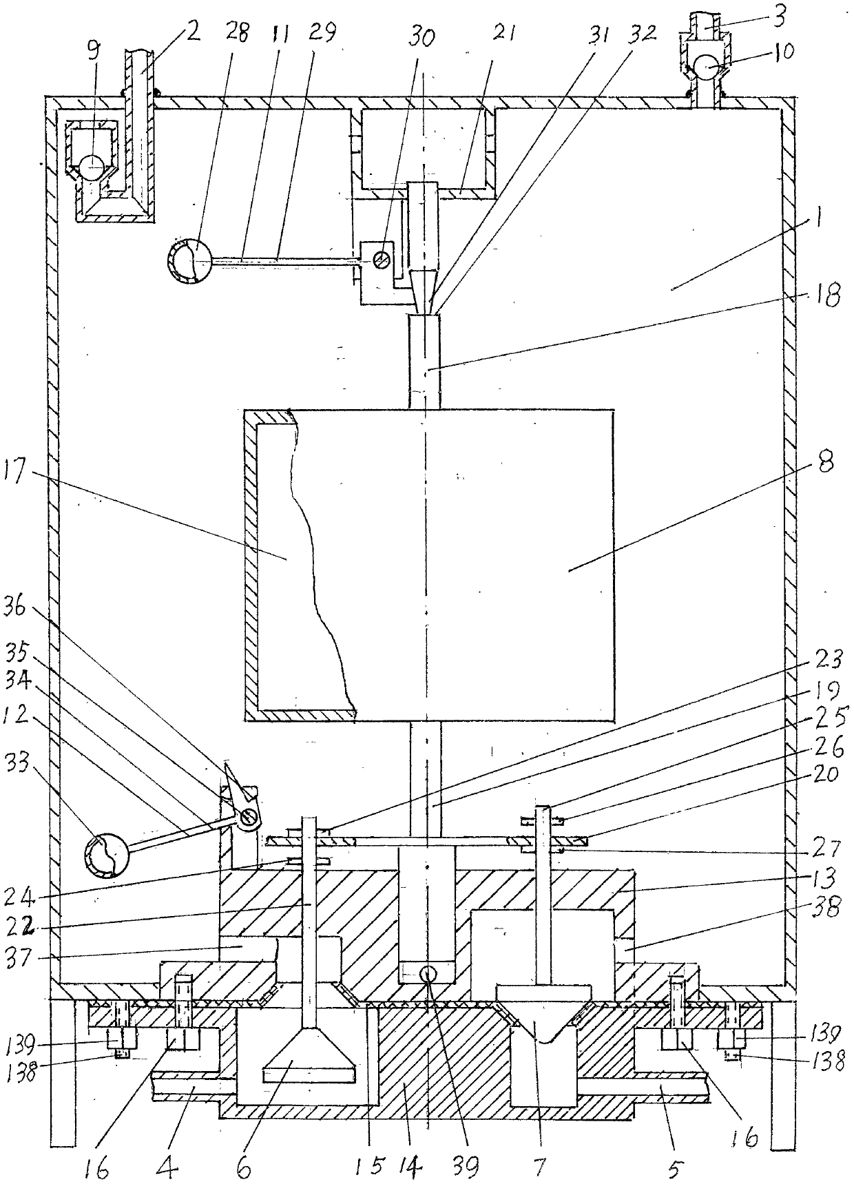
[0052] The water-gas mutual pressure box of embodiment 1 is as figure 1 shown. A water-air mutual pressure box, comprising a box body 1, an air inlet pipe 2, an air outlet pipe 3, a water inlet pipe 4 and a water outlet pipe 5, the air inlet pipe 2, the air outlet pipe 3, the water inlet pipe 4, and the water outlet pipe 5 are connected with the box body 1 and The inside of the box 1 is connected, the air inlet pipe 2 is connected in series with a check valve 9, the air outlet pipe 3 is connected in series with a check valve 10, the water inlet pipe 4 is connected in series with a valve 6, the water outlet pipe 5 is connected in series with a valve 7, and a float 8 is installed in the box body 1 , the float 8 cooperates with the valves 6, 7, the box body 1 is provided with the control mechanism 11, 12, the control mechanism 11, 12 cooperates with the float 8, the float 8 cooperates with the valve 6, 7 is the float 8 and the valve 6, 7 fit directly.

[0053] The intake pipe 2...

Embodiment 2

[0064] The water-gas mutual pressure box of embodiment 2 is as figure 2 shown. A water-air mutual pressure box, comprising a box body 1, an air inlet pipe 2, an air outlet pipe 3, a water inlet pipe 4 and a water outlet pipe 5, the air inlet pipe 2, the air outlet pipe 3, the water inlet pipe 4, and the water outlet pipe 5 are connected with the box body 1 and The inside of the tank 1 is connected, the inlet pipe 2 is connected in series with a valve 40, the outlet pipe 3 is connected in series with a valve 40, the water inlet pipe 4 is connected in series with a check valve 44, the outlet pipe 5 is connected in series with a check valve 45, and a float 8 is installed in the tank 1 , The float 8 cooperates with the valve 40, the box body 1 is provided with a control mechanism, the control mechanism cooperates with the float 8, and the cooperation between the float 8 and the valve 40 means that the float 8 directly cooperates with the valve 40.

[0065] The water inlet pipe 4...

Embodiment 3

[0076] The water-gas mutual pressure box of embodiment 3 is as image 3 , figure 2 shown. The water-gas mutual pressure tank of embodiment 3 is changed from the water-gas mutual pressure tank of embodiment 2. The water-air mutual pressure tank of embodiment 3 is mostly the same as the water-gas mutual pressure tank of embodiment 2, and there are only two differences. One is that the control mechanism is an elastic membrane automatic clamping control mechanism, and the other is that the outlet pipe 5 is not Any valve in series. This has just become described in the technical scheme, and the water-air mutual pressure box that the air inlet pipe is connected in series with valve, the air outlet pipe is connected in series with valve, the water inlet pipe is connected in series with check valve, and the water outlet pipe is not connected in series with any valve.

[0077] The elastic membrane automatic clamping control mechanism is arranged on the box body 1 inside the box bod...


PUM


Abstract

The invention relates to a water and air mutual pressing box and a water lifting system comprising the same. The water and air mutual pressing box which is reliable in work and high in work quality and capable of lifting water through air pressure or positive and negative compressed air produced by water pressure is provided, and the lifting system comprising the water and air mutual pressing box is provided. The water and air mutual pressing box comprises a box body, an air inlet pipe, an air outlet pipe, a water inlet pipe and a water outlet pipe. The air inlet pipe, the air outlet pipe, the water inlet pipe and the water outlet pipe communicate with the box body. In the air inlet pipe, the air outlet pipe, the water inlet pipe and the water outlet pipe, some are connected with valves in series, some are connected with check valves in series and a few of the pipes are not connected with any valves in series. A floater is installed in the box body and matched with the valves. The box body is provided with a control mechanism which is matched with the floater. The floater is directly matched with the valves. The water and air mutual pressing box can form the water lifting system through water power and can lift water in the low position to the high position to be used through flowing water kinetic energy of a water source with height differences. The water and air mutual pressing box and the water lifting system comprising the water and air mutual pressing box are free of electricity, oil and rotation and capable of ceaselessly bringing benefits to people day and night.

Description

technical field [0001] The invention relates to a water-gas mutual pressure tank and a water lifting system provided with the water-gas mutual pressure tank. The water-gas mutual pressure box is a box that can automatically lift the liquid one box at a time to a high place by using air pressure, or use the kinetic energy of the liquid to flow down from a high place to automatically output a box that is greater than or less than atmospheric pressure. box. The water lifting system is a system that can lift water from a low place to a high place for use. Background technique [0002] The application number is 200620117306.6, and the air compressor and the water press described in the Chinese patent called the automatic water level riser are exactly a kind of water-air mutual pressure tank. Both the air compressor and the water press have the following parts (not necessarily the original name) namely the box, the air inlet pipe, the air outlet pipe, the water inlet pipe, the w...

Claims


Application Information

Patent Timeline
Patent Type & Authority Patents(China)
IPC IPC(8): F04F1/00F04F1/08
CPCF04F1/00F04F1/08
Inventor 邢立天邢川明
Owner 云南淼汇能源科技有限公司
Why Eureka
Eureka Blog
Learn More