Traction wheel for casing pipe horizontal well tractor

A technology for horizontal wells and tractors, applied in the field of traction wheels, can solve the problems of decreased traction force, rapid wear of the outer gear ring, and inability to provide sufficient forward traction force, and achieves the effect of small load and reduced contact area.

Active Publication Date: 2016-06-15
WUHAN HAIWANG MECHANICAL & ELECTRICAL ENGTECH
View PDF5 Cites 2 Cited by
  • Summary
  • Abstract
  • Description
  • Claims
  • Application Information

AI Technical Summary

Problems solved by technology

[0003] (1) The outer tooth shape of the traction wheel does not match the inner wall of the casing in the circumferential direction of the casing, see figure 1 and figure 2 As shown, the addendum line of the existing traction wheel is a straight line, and only two ends of it are in contact with the bushing. Due to the uneven wear of the outer teeth of the traction wheel, the wear is accelerated, resulting in an intensified decline in the traction force, and the wear of the outer ring gear is relatively fast. As a result, the traction wheels cannot travel farther under the condition of large external load
[0004] (2) The outer tooth shape of the traction wheel does not match well with the inner wall of the casing in the axial direction of the casing, see image 3 As shown, the front and rear tooth surfaces of the external teeth of the existing traction wheel are symmetrical (α=β), and the extent of the occlusal casing inner wall in the advancing and retreating directions of the tractor is consistent, and it cannot provide greater advancement in the advancing direction of the tractor. power
Worn and slipping traction wheels will not be able to provide adequate forward traction

Method used


Image

  • Traction wheel for casing pipe horizontal well tractor
  • Traction wheel for casing pipe horizontal well tractor
  • Traction wheel for casing pipe horizontal well tractor

Examples


Embodiment Construction

[0032] The present invention will be described in further detail below in conjunction with the accompanying drawings.

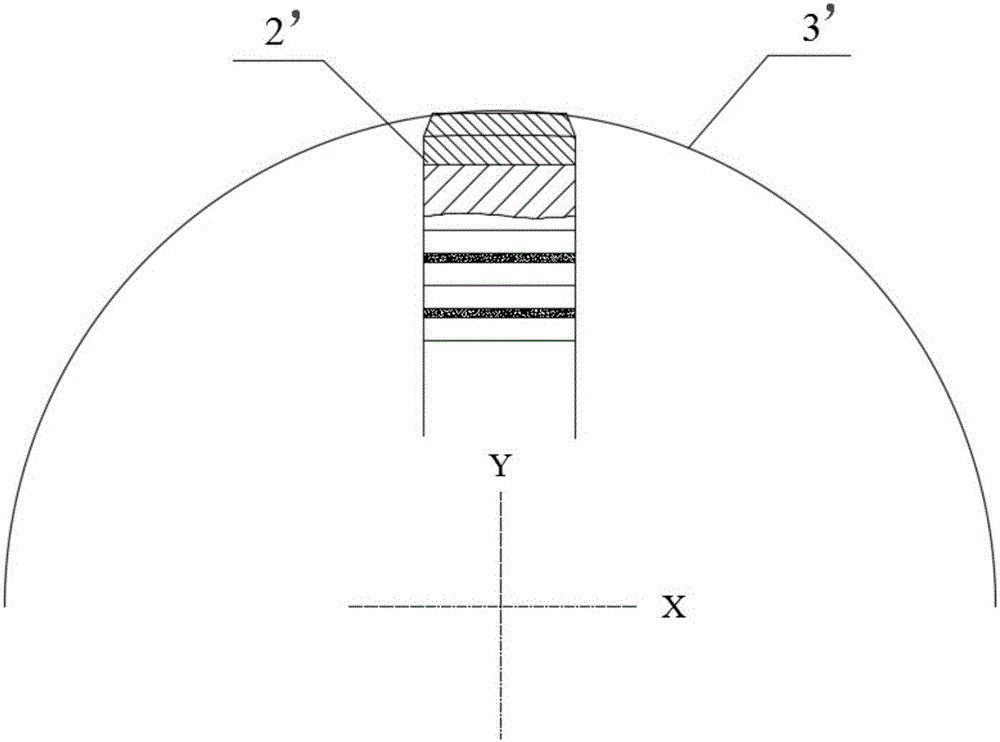
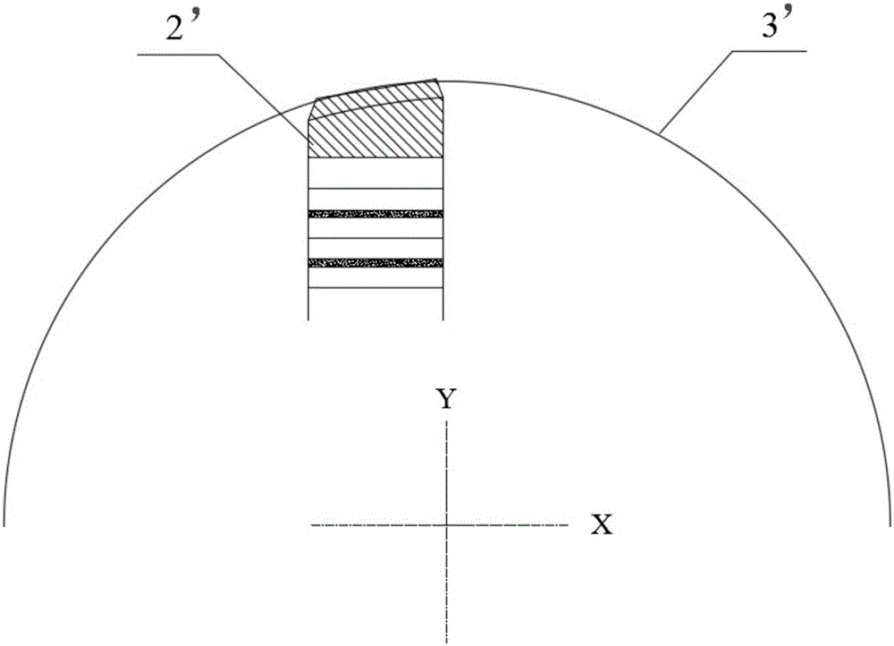
[0033] see Figure 4 As shown, the present invention provides a traction wheel of a casing horizontal well tractor, which includes a body 1 and an outer ring gear 2 .

[0034] The outer ring gear 2 is detachably sleeved on the body 1. Since the outer ring gear 2 is a wearing part, there is wear and tear in use, and it needs to be replaced after a period of use. save costs. see Figure 5 As shown, the teeth of the outer ring gear 2 are provided with multiple annular grooves 21 spaced apart from each other along the axial direction of the outer ring gear 2. The annular grooves 21 are arranged along the circumferential direction of the outer ring gear 2. The annular grooves 21 divides the outer gear ring 2 into a plurality of gear rings 22, and the end points of the addendum lines of all the gear rings 22 share a circular arc.

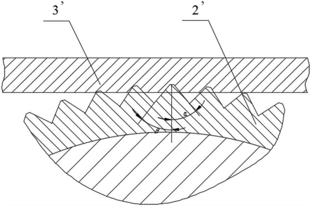
[0035] The shape of the tooth...


PUM


Abstract

The invention discloses a traction wheel for a casing pipe horizontal well tractor and relates to the field of wireline logging.The traction wheel comprises a body and an external gear ring, wherein the body is detachably sleeved with the external gear ring, a plurality of annular grooves are formed in teeth of the external gear ring in the axial direction of the external gear ring at intervals, the annular grooves are formed in the circumferential direction of the external gear ring and divide the external gear ring into a plurality of toothed rings, and the endpoints of tooth-tip lines of the toothed rings are located on the same arc.On one hand, the external tooth form is better matched with the inner wall of the sleeve in the circumferential direction of the sleeve, and external tooth abrasion is more uniform; on the other hand, the condition of external teeth being meshed with the inner wall of the sleeve is improved in the axial direction of the sleeve, and greater traction force can be provided compared with traditional traction wheels.

Description

technical field [0001] The invention relates to the field of wireline well logging, in particular to a traction wheel of a casing horizontal well tractor. Background technique [0002] As a pipeline robot, the casing horizontal well tractor is a delivery tool that is connected by cables to transport instruments and equipment in the casing. During the casing operation, when encountering a casing section with a large inclination and a horizontal section, the instrument and equipment cannot rely on their own gravity to advance. At this time, the casing horizontal well tractor provides power to push the instrument and equipment to continue moving forward. The power source of the existing casing horizontal well tractor can provide enough power, but there are two problems in the traction wheel as the final output traction force: [0003] (1) The outer tooth shape of the traction wheel does not match the inner wall of the casing in the circumferential direction of the casing, see ...

Claims


Application Information

Patent Timeline
IPC IPC(8): E21B47/00E21B23/14
CPCE21B23/14E21B47/00
Inventor 孙扬喆付永前杨诚颜晓淮孔繁军李伟周艳平李咸坤徐忠元刘情超张志华
Owner WUHAN HAIWANG MECHANICAL & ELECTRICAL ENGTECH
Why Eureka
Try Eureka