
Core-pulling cooling device for die-casting die

A technology of cooling device and die-casting mold, applied in the field of mold core-pulling structure, can solve the problems of poor cooling effect at the core-pulling position, inconvenient core-pulling operation, complex structure, etc., so as to avoid local overheating, good cooling effect, The effect of core pulling is easy to operate

Active Publication Date: 2016-06-15
NINGBO JUNLING MOLD TECH
View PDF10 Cites 4 Cited by
  • Summary
  • Abstract
  • Description
  • Claims
  • Application Information

AI Technical Summary

Problems solved by technology

[0004] The present invention overcomes the existing problems of complex structure, high cost, poor cooling effect on the core-pulling position, and inconvenient core-pulling operation of the existing die-casting cooling device, and provides a die-casting mold core-pulling cooling device, which has a simple structure , low cost, good cooling effect on the core-pulling position, easy core-pulling operation, saving mold design space

Method used


Image

  • Core-pulling cooling device for die-casting die
  • Core-pulling cooling device for die-casting die
  • Core-pulling cooling device for die-casting die

Examples


Embodiment

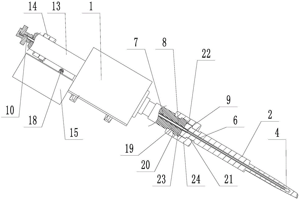
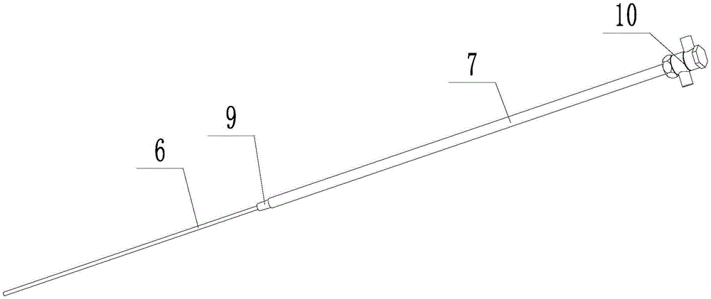
[0020] Embodiment: A kind of die-casting mold core-pulling cooling device (see attached Figures 1 to 4 ), including a piston cylinder 1, a core 2, and a cooling pipe 3. There is a cooling cavity 4 arranged along the axis in the core, and the bottom of the cooling cavity is close to the front end of the core. Transition block 5, the cooling pipe is movably connected to the piston cylinder, the cooling pipe includes an inner pipe 6 and an outer pipe 7, a liquid return gap 8 is provided between the outer wall of the inner pipe and the inner wall of the outer pipe, the inner pipe extends out of the front end of the outer pipe, and the inner pipe extends The part of the front end of the outer pipe is arranged in the cooling chamber, the front end of the inner pipe is arranged close to the bottom of the cooling chamber, the front end of the outer pipe is provided with a connecting part 9, the open end of the core and the quick release transition block is closely connected with the c...


PUM


Abstract

The invention discloses a core-pulling cooling device for a die-casting die. The core-pulling cooling device for the die-casting die aims at overcoming the defects that an existing die-casting cooling device is complex in structure and high in cost, the cooling effect of the core-pulling position is not good, and core pulling operation is not convenient. The core-pulling cooling device comprises a piston cylinder, a core and a cooling pipe, wherein a cooling cavity is formed in the core along the axis of the core, a quick-releasing transition block is connected between a telescopic rod of the piston cylinder and the core, and the cooling pipe is movably connected to the piston cylinder. The cooling pipe comprises an inner pipe and an outer pipe, a liquid return gap is formed between the outer wall of the inner pipe and the inner wall of the outer pipe, and the inner pipe stretches out of the front end of the outer pipe; the part, extending out of the front end of the outer pipe, of the inner pipe is arranged in the cooling cavity, the front end of the inner pipe is arranged close to the bottom end of the cooling cavity, and the front end of the outer pipe is provided with a connecting part. The open end, connected with the quick-releasing transition block, of the core is tightly connected with the connecting part, the rear end of the cooling pipe is connected with a connector, and the connector is provided with a liquid inlet connector body communicating with the inner pipe and a liquid return connector body communicating with a liquid outlet gap.

Description

technical field [0001] The invention relates to a mold core-pulling structure, more specifically, it relates to a die-casting mold core-pulling cooling device. Background technique [0002] Die casting is a precision casting method that presses molten metal into the mold through high pressure. The surface of the die casting is smooth and the precision is high. In most cases, the die casting can be assembled and applied without turning, even if there are threaded parts Can be cast directly. During the die-casting process, the die-casting parts need to be cooled to ensure that the core-pulling process is not easy to stick to aluminum and to ensure the roughness of the product surface. However, the currently commonly used die-casting cooling device has a complex structure, high cost, poor cooling effect on the core-pulling position, and inconvenient core-pulling operation. [0003] Chinese patent announcement number CN203061835U discloses a die-casting cooling water system, i...

Claims


Application Information

Patent Timeline
Patent Type & Authority Applications(China)
IPC IPC(8): B22D17/22
Inventor 彭伦强姚贤君胡宁安
Owner NINGBO JUNLING MOLD TECH
Learn More