
Wide-area fault recording system and synchronization method

A technology of fault recording and fault recording device, which is applied in information technology support systems, electrical components, circuit devices, etc., and can solve problems such as different thresholds for setting values, high construction costs, and inability to meet communication bandwidth requirements, etc.

Active Publication Date: 2016-06-08
NR ELECTRIC CO LTD +1
View PDF2 Cites 19 Cited by
  • Summary
  • Abstract
  • Description
  • Claims
  • Application Information

AI Technical Summary

Problems solved by technology

[0003] (1) When a fault occurs, only some fault recorders start the wave recording, and the other part of the wave recorders do not start the wave recording because the fault characteristics are not obvious, or the setting threshold is high;
[0004] (2) All fault recorders started wave recording when the fault occurred, but due to different fault characteristics and different setting thresholds, the wave recording was not started synchronously;
The E1 network is affected by the dynamic generation of routing links, and the communication delay has a large discreteness; and the communication bandwidth of the E1 network is only 2Mbps, which cannot meet the communication bandwidth requirements of IEC61850-9-2
In this case, for the synchronization method in the above patent, it is necessary to build a dedicated wide-area process layer communication network, and the construction cost is too high
[0008] Therefore, in response to the above needs, there is no cost-effective solution in the public information

Method used


Image

  • Wide-area fault recording system and synchronization method
  • Wide-area fault recording system and synchronization method
  • Wide-area fault recording system and synchronization method

Examples


Embodiment Construction

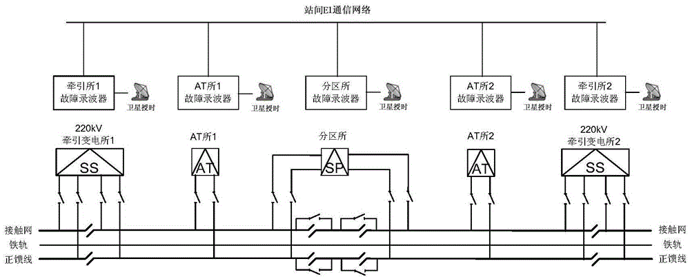
[0024] The following will be combined with image 3 , the technical solution of the present invention will be described in detail.

[0025] image 3 It is a configuration diagram of the wide-area synchronous wave recording scheme for the traction power supply system of the high-speed railway. The high-speed railway traction power supply system consists of traction substations, AT substations (AT substations) and subregional substations (subdivision substations), and the distance between the three substations is within the range of 10km to 15km. The catenary and the positive feeder together provide power for the locomotives of the EMU, and are connected to the above three types of substations at the same time. Therefore, when the catenary or the positive feeder fails, the current and voltage of the three types of substations in the traction power supply system will have different fault characteristics. In order to be able to comprehensively analyze the fault situation of the...


PUM


Abstract

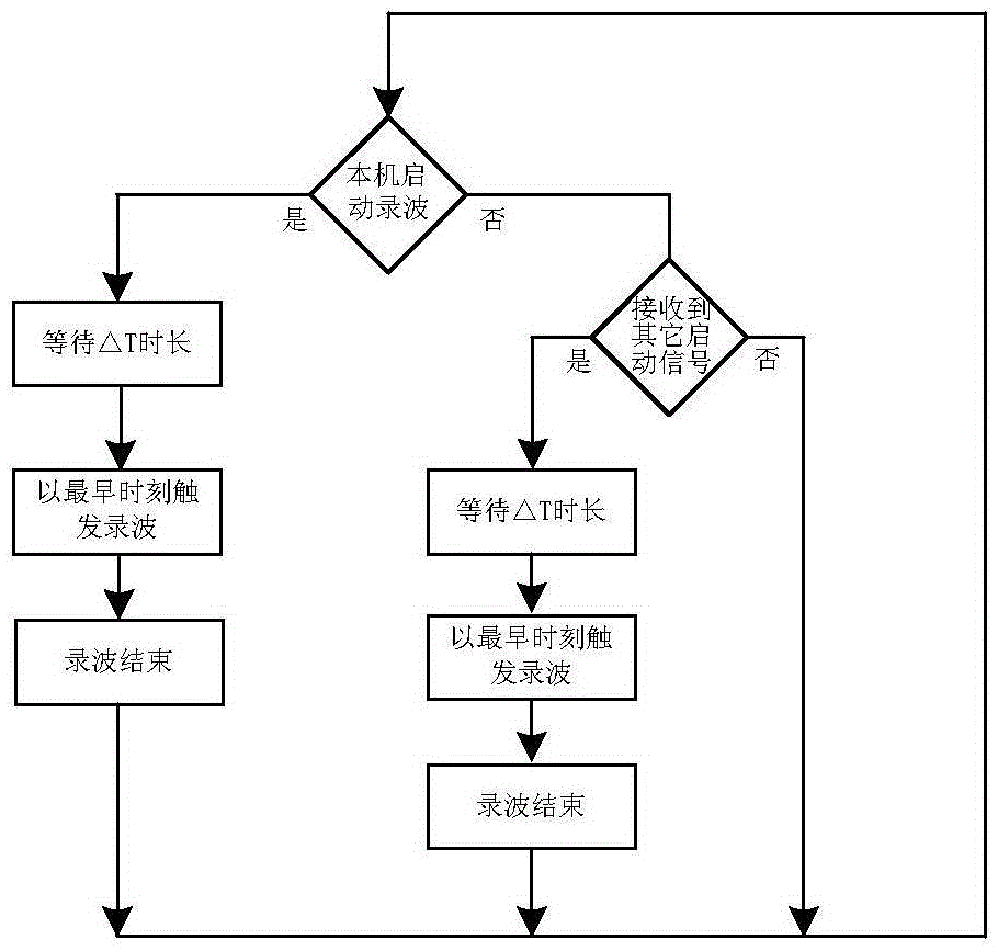
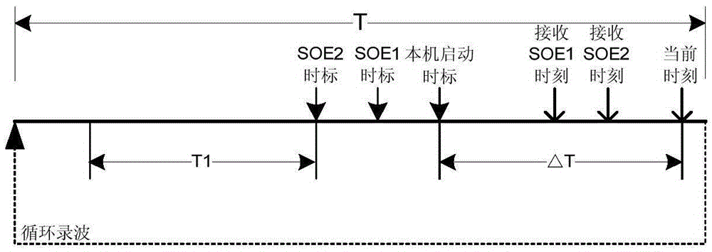
The invention discloses a wide-area fault recording system and a synchronization method. The method includes the steps that fault recording devices are arranged on all geographically-dispersed transformer substations respectively; all the fault recording devices are connected to a communication network, and the different devices in same working groups can be communicated through the network; after self-starting criterions of all the fault recording devices are started, the fault recording devices send starting signals (network starting signals) to the other devices in the same working groups, and absolute time marks of starting moments are carried in the sent signals; delta T time begins to be waited, the earliest starting moments in all the starting signals (the starting signals include the self-starting signals and the network starting signals) in the delta T time are compared and selected, and wave files are started to be stored and recorded according to the preset recording regulation from the moments. The requirement of the synchronization recording method for the real-time performance of the communication network is low, wide-area synchronization recording can be achieved through an existing non-real-time communication network, the investment of special real-time channels is saved, and the large practical value is achieved.

Description

technical field [0001] The invention relates to a remote synchronous wave recording method in a wide area, which is suitable for various types of power supply systems that need to realize wide area synchronous wave recording. Background technique [0002] In the traditional oscilloscope configuration scheme, fault oscilloscopes are usually arranged in different geographically dispersed substations, and the start-up conditions of each device are set independently of each other. Once a fault occurs in the power supply system, the distributed fault recorders will independently judge whether to start the record. In this way, the following two situations will occur: [0003] (1) When a fault occurs, only some fault recorders start the wave recording, and the other part of the wave recorders do not start the wave recording because the fault characteristics are not obvious, or the setting threshold is high; [0004] (2) All fault recorders started wave recording when the fault oc...

Claims


Application Information

Patent Timeline
IPC IPC(8): H02J13/00
CPCH02J13/0013Y04S10/16Y02E60/00
Inventor 魏巍侯炜陈俊王亮刘伟陈佳胜沈全荣
Owner NR ELECTRIC CO LTD
Learn More