Anti-delay all-impedance relay and action method and device
A relay, full-impedance technology, applied in the field of devices, inverse-delay full-impedance relays and action methods, can solve the problem that fixed-delay impedance relays cannot automatically adjust the action time, etc., so as to improve action reliability, short-circuit points, and faults. light effect
- Summary
- Abstract
- Description
- Claims
- Application Information
AI Technical Summary
Problems solved by technology
Method used
Image
Examples
Embodiment 1
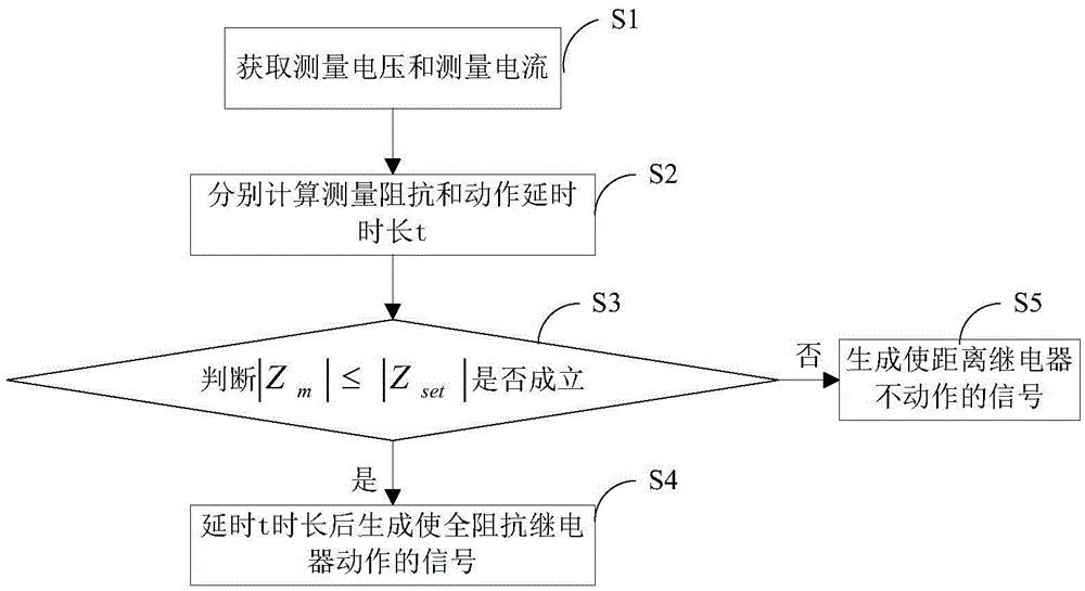
[0043] This embodiment provides an action method for anti-delay full-impedance relays. For example, it is applied to anti-time-delay full-impedance relays. According to the size of the measured value, the measured value is small and the action is fast; the measured value is large and the action is slow. The impedance relay is called Anti-time-delay impedance relays, such as figure 1 As shown, the anti-time-delay full-impedance relay action method includes the following steps:
[0044] S1. Obtain the measured voltage and measure the current
[0045] S2. Calculate the measured impedance Z according to the following formula m and action delay time t: Among them, Z set is the setting impedance, k 1 is the first tuning coefficient, R is the second tuning coefficient, T set is the time setting factor;
[0046] S3. Judgment|Z m |≤|Z set |Whether to be established; when|Z m |≤|Z set|, go to step S4; otherwise, go to step S5.
[0047] S4. Delaying for a period of time...
Embodiment 2
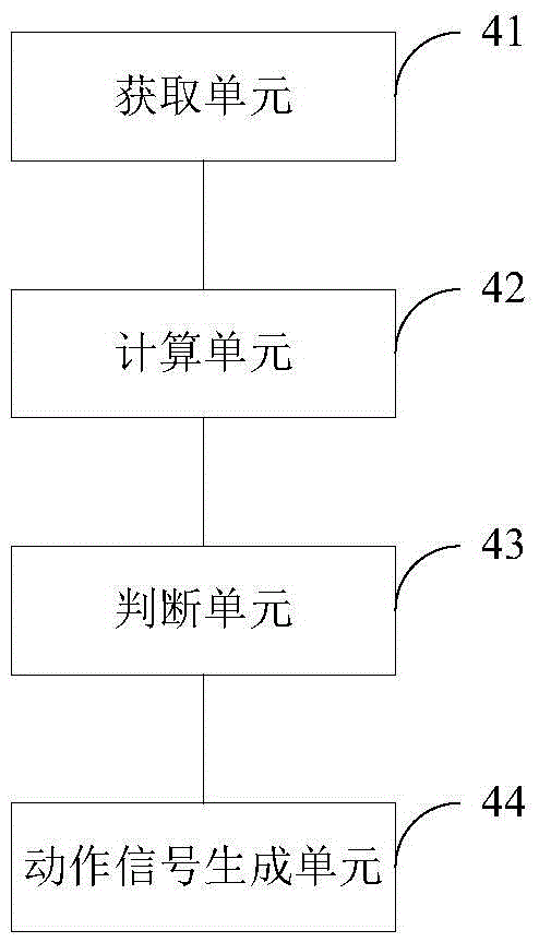
[0052] Corresponding to the above-mentioned embodiment 1, this embodiment provides an anti-time-delay full-impedance relay operating device, such as figure 2 shown, including:
[0053] Acquisition unit 41, used to obtain the measurement voltage and measure the current
[0054] Calculation unit 42, for calculating the measurement impedance Z according to the following formula respectively m and action delay time t: Among them, Z set is the setting impedance, k 1 is the first tuning coefficient, R is the second tuning coefficient, T set is the time setting factor;
[0055] Judgment unit 43, for judging |Z m |≤|Z set |Is it established?
[0056] Action signal generation unit 44, for when |Z m |≤|Z set |, after a delay of t, a signal is generated to make the full-impedance relay act.
[0057] Preferably, k 1 The value range of R is 0.1~100, the value range of R is 0.01~3, and T set The value range is 1~2.
[0058] The above anti-delay full-impedance relay opera...
Embodiment 3
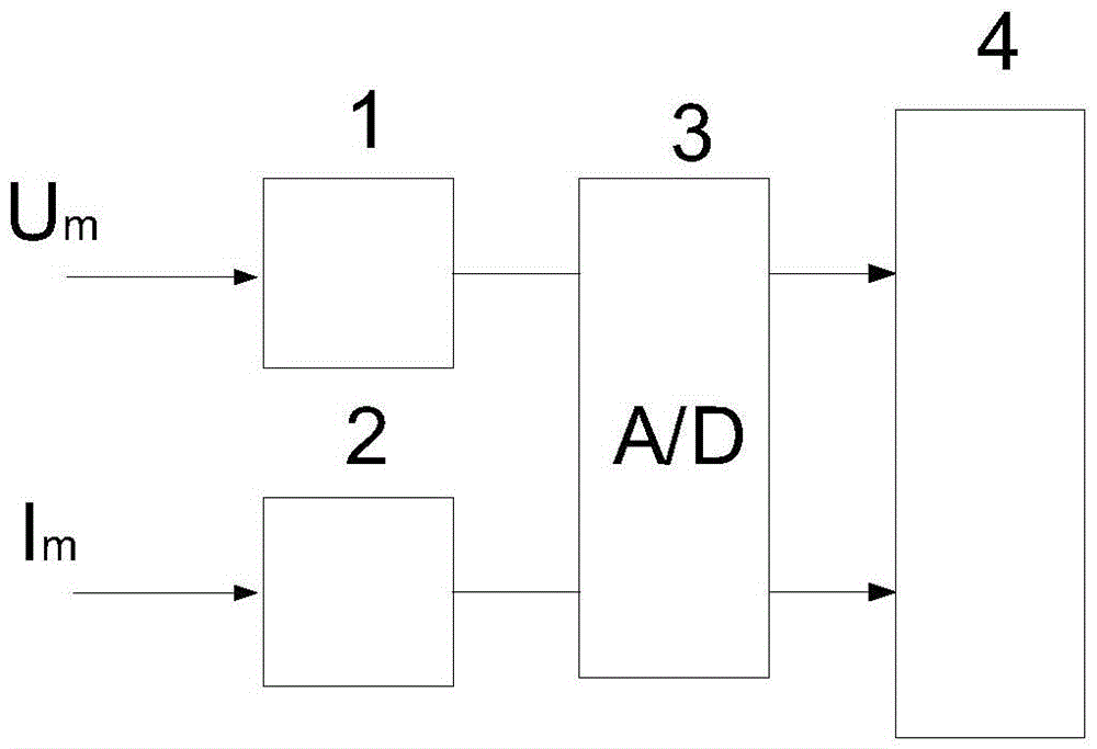
[0060] This embodiment provides an anti-time-delay full-impedance relay, such as image 3 shown, including:
[0061] Potential transformer 1 for receiving the measuring voltage The measured voltage Convert into a voltage suitable for the A / D converter 3 and output it;
[0062] Current / voltage converter 2 for receiving the measuring current The measured current Convert into a voltage suitable for the A / D converter 3 and output it;
[0063] The A / D converter 3 is used to convert the received voltage output by the voltage transformer 1 and the current / voltage converter 2 into a digital quantity and output it;
[0064] Processor 4 comprises anti-time-delay full-impedance relay action device, and said anti-time-delay full-impedance relay action device includes:
[0065] An acquisition unit, configured to acquire the measurement voltage according to the digital quantity output by the A / D converter 3 and measure the current
[0066] Calculation unit for calculating the...
PUM
 Abstract
Description
Claims
Application Information
 - R&D
- Intellectual Property
- Life Sciences
- Materials
- Tech Scout
- Unparalleled Data Quality
- Higher Quality Content
- 60% Fewer Hallucinations
Browse by: Latest US Patents, China's latest patents, Technical Efficacy Thesaurus, Application Domain, Technology Topic, Popular Technical Reports.
© 2025 PatSnap. All rights reserved.Legal|Privacy policy|Modern Slavery Act Transparency Statement|Sitemap|About US| Contact US: help@patsnap.com


