Optical component and timepiece
A technology for optical components and clocks, applied in optical components, optics, clocks, etc., can solve problems such as inability to obtain anti-reflection functions
- Summary
- Abstract
- Description
- Claims
- Application Information
AI Technical Summary
Problems solved by technology
Method used
Image
Examples
no. 1 Embodiment approach
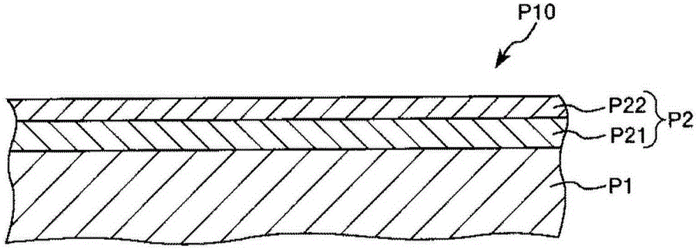
[0042] figure 1 It is a cross-sectional view schematically showing the first embodiment of the optical component of the present invention.
[0043] Such as figure 1 As shown, the optical component P10 of this embodiment includes a base material P1 and an antireflection film P2.
[0044] In addition, the antireflection film P2 is provided with a titanium oxide layer P21 and a silicon oxide layer P22. The titanium oxide layer P21 is mainly composed of titanium oxide and contains a layer selected from the group consisting of Nb, Si, Zr, Ta, Al, and Hf. One or two or more elements are used as subcomponents, and the silicon oxide layer P22 is mainly composed of silicon oxide.
[0045] With such a configuration, the optical member P10 can be sufficiently excellent in translucency and mechanical strength, and can obtain an excellent antireflection function. And, thereby, the optical component P10 can stably exhibit desired optical characteristics.
[0046] The reason why this exc...
no. 2 Embodiment approach
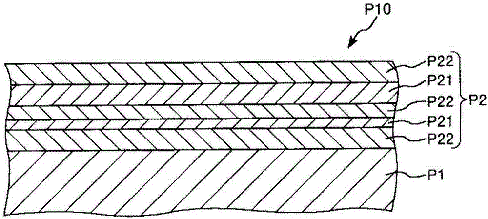
[0100] figure 2 It is a cross-sectional view schematically showing a second embodiment of the optical component of the present invention. In the following description, differences from the above-described embodiment will be mainly described, and descriptions of the same matters will be omitted.
[0101] Such as figure 2 As shown, the optical component P10 of this embodiment includes the base material P1 and the antireflection film P2, but the configuration of the antireflection film P2 is different from that of the above-mentioned first embodiment. That is, in the present embodiment, the antireflection film P2 has a plurality of titanium oxide layers P21 and a plurality of silicon oxide layers P22, and has a structure in which these layers are alternately arranged.
[0102] Thus, in the present invention, the antireflection film may have two or more layers, at least one of a titanium oxide layer and a silicon oxide layer.
[0103] Thereby, the antireflection function can ...
Embodiment 1
[0165] A cover glass as an optical component was manufactured by the method shown below.
[0166] First, a plate material (glass plate) made of sapphire glass is prepared as a base material (base material preparation process), and necessary parts are cut and polished. The base material after cutting and grinding was approximately disc-shaped, and had a size of diameter: 30 mm×thickness: 1 mm.
[0167] Next, an ultraviolet irradiation treatment of irradiating ultraviolet rays having a wavelength of 248 nm was performed on the surface of the substrate on which the antireflection film was to be formed.
[0168] Next, by using titanium dioxide (TiO 2 ) and niobium oxide (Nb 2 o 5 ) mixture as a deposition source by ion beam-assisted deposition to form a titanium oxide layer on a base material (titanium oxide layer formation process) to obtain a cover glass as an optical component. The thickness of the formed titanium oxide layer was 100 nm, the content of titanium (Ti) contain...
PUM
| Property | Measurement | Unit |
|---|---|---|
| thickness | aaaaa | aaaaa |
| thickness | aaaaa | aaaaa |
| thickness | aaaaa | aaaaa |
Abstract
Description
Claims
Application Information
 - R&D Engineer
- R&D Manager
- IP Professional
- Industry Leading Data Capabilities
- Powerful AI technology
- Patent DNA Extraction
Browse by: Latest US Patents, China's latest patents, Technical Efficacy Thesaurus, Application Domain, Technology Topic, Popular Technical Reports.
© 2024 PatSnap. All rights reserved.Legal|Privacy policy|Modern Slavery Act Transparency Statement|Sitemap|About US| Contact US: help@patsnap.com


