
Double-insertion security door and externally-hung locking device

A locking device and anti-theft door technology, applied in the direction of preventing theft, building locks, door/window accessories, etc., to achieve the effects of improved destructive ability, reliable operation of locks, and improved resistance to damage

Active Publication Date: 2016-06-08
BEIHUA UNIV
View PDF6 Cites 54 Cited by
  • Summary
  • Abstract
  • Description
  • Claims
  • Application Information

AI Technical Summary

Problems solved by technology

[0008] In order to overcome the drawbacks of the above-mentioned key-driven lockbolt lock and lockbolt integrated locking mechanism, and the lockset and lockbolt split locking mechanism that uses the handle of the lockset as a stop mechanism to independently drive the lockbolt and the lockbolt split locking mechanism, and solve the above two inventions Patented mutual assembly, drive connection and other issues, the present invention provides a double-insert anti-theft door and an external locking device with completely different or completely opposite structural features and connection relationships: the lock is fixed on the mounting frame of the door reinforcement plate , with a certain distance from the side of the door leaf; the lock, the main lock bolt and the lock tongue are neither integrated nor purely split, but an external hanging type that is movably connected to the outside of the lock body; it is driven by a handle, but can The idling handle does not drive the lock bolt alone and has no connection with the lock. On the contrary, the handle drives the lock bolt through the lock and is integrated with the lock

Method used


Image

  • Double-insertion security door and externally-hung locking device
  • Double-insertion security door and externally-hung locking device
  • Double-insertion security door and externally-hung locking device

Examples


Embodiment Construction

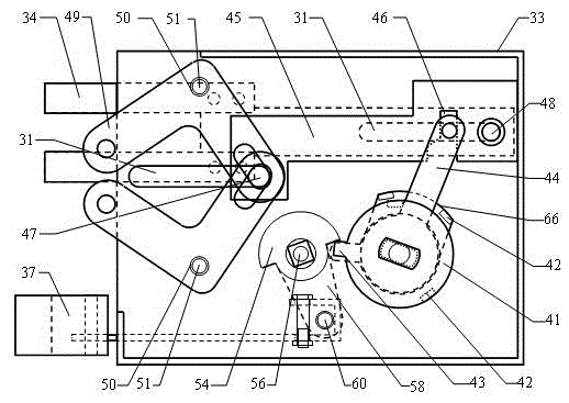
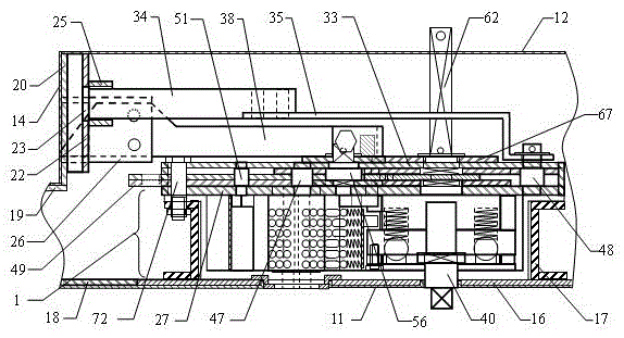
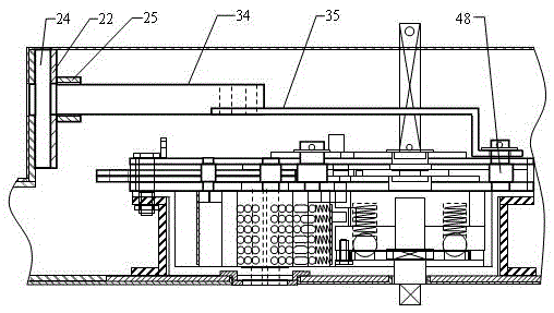
[0071] Combine below Figure 1 to Figure 40 The present invention is further described.

[0072] exist figure 1 , 2 , 31, 32, the reinforcing plate 16 is fixed on the door leaf outer panel 11, the mounting frame 17 is fixed on the reinforcing plate 16, and the lock cylinder fixed cross mechanical anti-theft lock 1 is installed on the installation by the lock body bolt 72 and the lock body mounting hole 32. on the frame 17, and at a certain distance from the side 14 of the door leaf, the outer end of the camshaft 40 protrudes beyond the outer panel 11 of the door leaf, the longitudinal plate 18 is fixedly installed on the side 14 of the door leaf and the outer panel 11 of the door leaf, and the liner 22 is fixed On the double board 20 of the longitudinal plate 18, the short pipe 25 is fixed on the lining board 22, the inner wall of the short pipe 25 is aligned with the lining board jack 23, and the square pipe 26 is fixed on the double board 20, and the inner wall of the squ...


PUM


Abstract

The invention discloses a double-insertion security door and externally-hung locking device, and relates to the field of security doors and mechanical security locks. In a technical scheme that two patented products, namely a double-insertion security door and a lock core-fixed cross-shaped mechanical security lock, are matched and combined for use, and a special driving connection way is also adopted. The double-insertion security door and externally-hung locking device is mainly characterized in that a lock is mounted inside a door leaf, and is separated from the side of the door leaf by a certain distance; a main lock latch and a lock tongue are independently mounted between the lock and the inner plate surface of the door leaf, and are movably connected with an extending part of a lock driving component only, namely are externally hung outside the lock body; the door leaf is unlocked and locked by rotating a handle integrally assembled with the lock movably and capable of idling, and the stroke of the main lock latch can be increased to more than double; only one knob is used for driving the locking device indoors, so that operation is simple and quick; the anti-prying and damage-preventing performance of the door leaf is also broken through while the lock cannot be unlocked technically and can resist forcible unlocking and damage.

Description

technical field [0001] The invention relates to the field of anti-theft safety doors and mechanical anti-theft locks, in particular to a double-insert anti-theft door and an external hanging locking device. Background technique [0002] The locking device of the anti-theft door is mainly composed of a lock cylinder, a driving mechanism, a connecting mechanism, a lock bolt, a dead bolt and a corresponding door frame socket. The lock bolt and the auxiliary lock bolt indirectly driven by the connection mechanism such as the sky-earth rod, driven by the driving mechanism, the main lock bolt and the dead bolt move horizontally, the sky-earth rod moves vertically, and the converter converts the vertical movement of the sky-earth rod into the corresponding auxiliary lock bolt horizontal movement. The locking or opening of the door leaf is realized by driving each locking bolt and deadbolt to be inserted into or drawn out from the socket of the door frame. [0003] The anti-theft ...

Claims


Application Information

Patent Timeline
IPC IPC(8): E06B5/11E05B15/00E05B63/14E05B3/00E05B17/22E05B17/20
CPCE05B3/00E05B15/00E05B17/2084E05B17/22E05B63/146E06B5/11
Inventor 吕雪寒叶延亮曹俊标
Owner BEIHUA UNIV
Learn More