
Ignition device of water-coal slurry cold wall gasifier

An ignition device and coal-water slurry technology, applied in the details of gasification device, gasification process, granular/powdered fuel gasification, etc., can solve the problem of affecting the working performance and service life of the coal-water slurry process burner, and loss of refractory materials The thermal insulation and heat storage function of the layer and the inability to ignite the cold-wall gasifier with water-coal slurry have achieved the effect of solving the problem of ignition and start-up, improving the working performance and service life, and reducing the cost.

Inactive Publication Date: 2016-06-08
XIAN AEROSPACE SOURCE POWER ENG CO LTD
View PDF4 Cites 3 Cited by
  • Summary
  • Abstract
  • Description
  • Claims
  • Application Information

AI Technical Summary

Problems solved by technology

[0004] However, after the hot fireplace is transformed into a cold fireplace, the gasification furnace loses the heat preservation and heat storage function of the refractory material layer, and the water-cooled wall also has the effect of rapidly cooling the furnace. The working method of the coal-water slurry process burner cannot be used for the ignition of the coal-water slurry cold-wall gasifier, and it is urgent to adopt a new ignition method to ignite the coal-water slurry cold-wall gasifier
[0005] At present, although there is an integrated coal-water slurry burner that utilizes the coal slurry channel and oxygen channel of the coal-water slurry burner to inject fuel gas and oxygen for drying, but because the coal-water slurry process burner is aimed at the coal-water slurry and oxygen The flow characteristics are designed. When the fuel gas and oxygen are put into operation, the range of working conditions changes greatly. In the actual use of the integrated coal-water slurry burner, the head of the coal-water slurry burner often burns severely during the drying stage. Corrosion greatly affects the working performance and service life of the coal water slurry process burner

Method used


Image

  • Ignition device of water-coal slurry cold wall gasifier

Examples


Embodiment Construction

[0027] In order to make the technical means, creative features, goals and effects achieved by the present invention easy to understand, the present invention will be further described below in conjunction with specific illustrations.

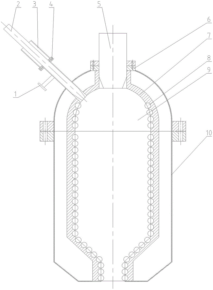
[0028] like figure 1 As shown, an ignition device for a coal-water slurry cold-wall gasifier includes: a coal-water slurry cold-wall gasifier 1; a furnace 9 nested in the coal-water slurry cold-wall gasifier , a chamber for coal-water slurry and oxygen combustion is formed in the furnace; a guide port is arranged at the end of the furnace, and the guide port is connected to a coal-water slurry process burner 5, and the coal-water slurry process burner 5 passes through the water Coal slurry burner interface 4 is fixed on the described coal-water slurry cold-wall gasifier; it also includes a guide channel, and the guide channel runs through the coal-water slurry cold-wall gasifier and the inner wall of the furnace successively, and is connected wi...


PUM


Abstract

The invention discloses an ignition device of a water-coal slurry cold wall gasifier. The ignition device comprises the water-coal slurry cold wall gasifier and a hearth arranged in the water-coal slurry cold wall gasifier in a nested mode. A chamber for water-coal slurry and oxygen combustion is formed in the hearth, a guide opening is formed in the end of the hearth and connected with a water-coal slurry process burner, and the water-coal slurry process burner is fixed to the water-coal slurry cold wall gasifier through a water-coal slurry burner connector. The ignition device further comprises a guide channel. The guide channel penetrates through the water-coal slurry cold wall gasifier and the inner wall of the hearth in sequence and is communicated with the chamber formed in the hearth, and an ignition startup burner is arranged in the guide channel in a nested mode and moves freely in the guide channel. According to the ignition device, ignition operation is simple, system transformation is small, cost is low, stability is good, and the service life of the burners is long.

Description

technical field [0001] The invention belongs to the coalification process field of pressurized gasification of coal-water slurry, and in particular relates to an ignition device for a cold-wall gasifier of coal-water slurry. Background technique [0002] At present, most of the gasifiers using the coal-water slurry gasification process in my country are hot fireplaces with refractory materials laid on the inner wall of the furnace. On the one hand, in order to protect the pressure steel shell; on the other hand, in order to use refractory bricks for heat storage during start-up, and complete the ignition process of coal-water slurry. However, due to the limitations of its own performance, refractory materials need to be replaced on a large scale every once in a while. The cost of replacing refractory materials reaches tens of millions of yuan every year, and the loss of production due to shutdown maintenance is even more unavoidable. Estimate. In order to avoid this proble...

Claims


Application Information

Patent Timeline
IPC IPC(8): C10J3/48
CPCC10J3/48C10J2200/152C10J2300/0959
Inventor 薛康吴远刚刘自涛陈杰
Owner XIAN AEROSPACE SOURCE POWER ENG CO LTD
Learn More