Combined double electromagnetic gas injection device

An injection device, dual electromagnetic technology, applied in the direction of fuel supply device, charging system, combustion engine, etc., can solve the problems of affecting control accuracy, large circulating injection volume, and unstable injection, so as to ensure reliability and stability, The effect of simplified engine structure and flexible jet pattern

Active Publication Date: 2017-12-01
HARBIN ENG UNIV
View PDF4 Cites 0 Cited by
  • Summary
  • Abstract
  • Description
  • Claims
  • Application Information

AI Technical Summary

Problems solved by technology

[0003] The current in-cylinder direct injection gas injection system mainly controls the movement of the needle valve through the internal integrated high-speed solenoid valve to realize the opening and closing of the gas injection valve, which can control the timing and amount of gas injection, and has good energy saving and emission reduction effect, but there are some problems: First, the single-cylinder power coverage of the engine is large, and the injection device with a large flow nozzle has a large amount of circulating air injection, but the injection is unstable and the control accuracy of the small flow gas injection is low, which affects the engine at part load. The lower the control accuracy of the injection volume; the injection device using a small flow nozzle has high precision for small flow gas injection, but it does not meet the demand for gas injection volume in the high-power working condition of the engine. Therefore, only a single-nozzle injection device is used to match the engine. The power is limited, which cannot meet the power of the engine under different working conditions and the power requirements of serialized engines; second, a single high-speed solenoid valve only has two working states of on and off, and cannot complete the multi-mode control of gas injection; third, with the With the movement of the needle valve, the gas leaks upward along the gap between the needle valve coupler, and the leaked gas enters the control chamber, resulting in a decrease in the gas injection pressure and injection rate, which seriously affects the working stability of the gas injection device.

Method used


Image

  • Combined double electromagnetic gas injection device
  • Combined double electromagnetic gas injection device
  • Combined double electromagnetic gas injection device

Examples


Embodiment Construction

[0022] Below in conjunction with legend the present invention is described in more detail:

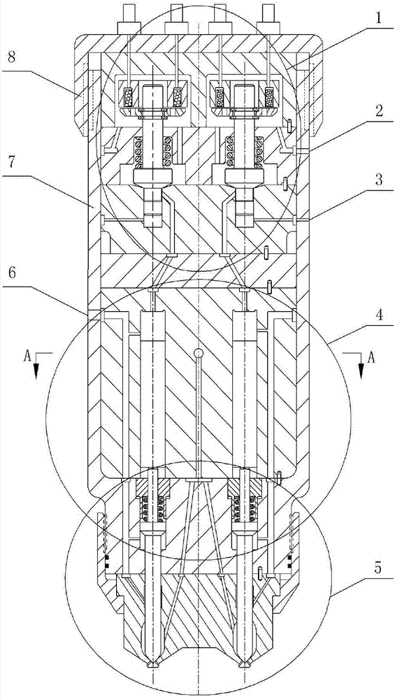
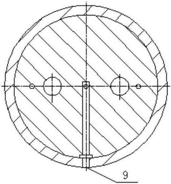
[0023] combine Figure 1(a) to Figure 1(b) , The combined double electromagnetic gas injection device of the present invention is mainly composed of a double solenoid valve part 1, a double control piston part 4, a double needle valve nozzle part 5, an injection device body 7 and an upper end cover 8 of the injection device. The injection device body 7 has a first low-pressure oil drain port 2, a second low-pressure oil drain port 3, a control oil inlet 6, a gas inlet 9, etc., and the oil passage at the gas inlet is shown in Figure 1(b).

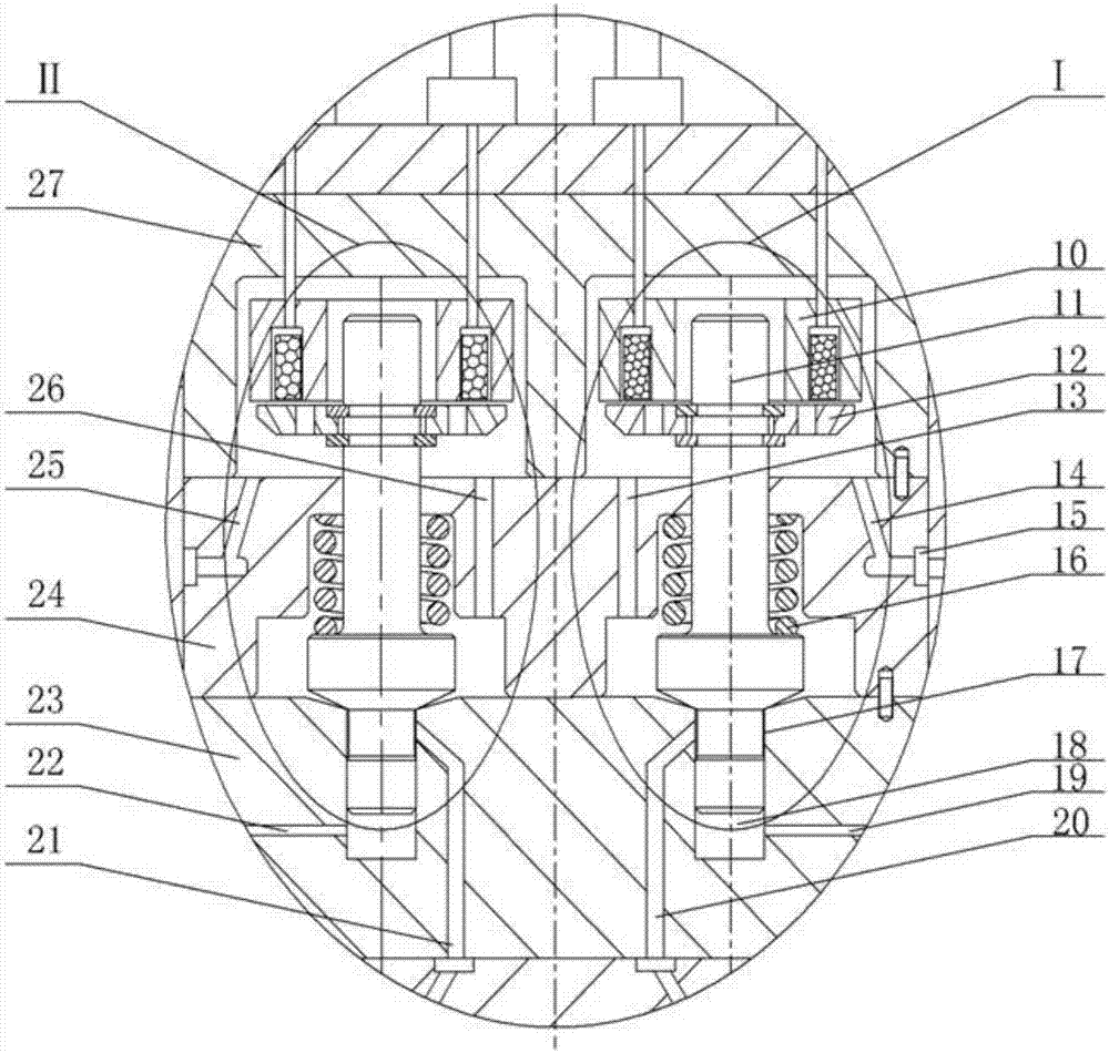
[0024] combine figure 2, double solenoid valve part 1 mainly includes solenoid valve Ⅰ, solenoid valve Ⅱ, solenoid valve body 27, solenoid valve spring seat 24, valve stem sealing base 23, etc. The structure and installation method of solenoid valve Ⅰ and solenoid valve Ⅱ are the same. The device is symmetrically distributed and shares the electrom...


PUM


Abstract

The invention provides a combined type dual-electromagnetic-valve gas injection device which comprises a dual-electromagnetic-valve part, a dual-control-piston part, a dual-needle-valve nozzle part, an injection device upper end cover and an injection device shell. A high-pressure control oil inlet, two low-pressure oil drainage openings and a gas inlet are formed in the injection device shell. The dual-electromagnetic-valve part is composed of two electromagnetic valves, an electromagnetic valve body, an electromagnetic valve spring seat and an electromagnetic valve sealing base. The dual-control-piston part comprises a piston sleeve, a first piston, a first piston control cavity, a first needle valve control cavity, a second needle valve control cavity, a second piston and a second piston control cavity. The dual-needle-valve nozzle part is composed of a first needle valve, a second needle valve, a needle valve base, a nozzle sleeve, a first nozzle sealing ring belt and a second nozzle sealing ring belt. According to the combined type dual-electromagnetic-valve gas injection device, gas leakage and static leakage of control oil are avoided, the two electromagnetic valves are adopted for separately controlling two nozzles for gas injection, and the requirements for the power of engines under different working conditions and the power of series engines are met.

Description

technical field [0001] The invention relates to a gas injection device for an engine, in particular to a combined double electromagnetic gas injection device applied to a dual-fuel engine. Background technique [0002] With the continuous consumption of fossil fuels and the increasingly stringent emission regulations of internal combustion engines, the development of engines is facing the dual pressure of energy crisis and environmental pollution. The use of alternative fuels is an effective means to solve both energy problems and environmental pollution. Natural gas and petroleum gas have become the main substitute fuels for internal combustion engines due to their abundant resources, low price, clean combustion, and high calorific value. [0003] The current in-cylinder direct injection gas injection system mainly controls the movement of the needle valve through the internal integrated high-speed solenoid valve to realize the opening and closing of the gas injection valve...

Claims


Application Information

Patent Timeline
Patent Type & Authority Patents(China)
IPC IPC(8): F02M21/02
CPCF02M21/0227F02M21/0245F02M21/0254F02M21/0257F02M21/0263Y02T10/30
Inventor 范立云董晓露杨立平赵建辉彭怀利石勇
Owner HARBIN ENG UNIV
Why Eureka
Try Eureka