Combined type pressurizing double-electromagnetic-valve gas injection device

A technology of injection device and booster solenoid valve, which is applied in oil supply device, charging system, combustion engine, etc., can solve the problems of unstable injection, limited engine power, and large coverage, and achieve the effect of flexible injection law.

Active Publication Date: 2016-06-01
HARBIN ENG UNIV
View PDF4 Cites 9 Cited by
  • Summary
  • Abstract
  • Description
  • Claims
  • Application Information

AI Technical Summary

Problems solved by technology

[0003] The current in-cylinder direct injection gas injection system mainly controls the movement of the needle valve through the internal integrated high-speed solenoid valve to realize the opening and closing of the gas injection valve, which can control the timing and amount of gas injection, and has good energy saving and emission reduction effect, but there are some problems: First, the single-cylinder power coverage of the engine is large, and the injection device using a large-flow nozzle has a large injection volume, but the injection is unstable and the control accuracy of the small-flow gas injection is low, which affects the engine under partial load. The control accuracy of the injection volume; while the injection device using a small flow nozzle has high precision for small flow gas injection, but it does not meet the demand for gas injection volume in the high-power working condition of the engine. Therefore, only a single-nozzle injection device is used to match the engine power Limited, it cannot meet the power of the engine under different working conditions and the power requirements of serialized engines; second, in order to improve the degree of gas mixing, a supercharging device is usually used to boost the gas to increase the gas injection pressure. Compared with liquid fuel, If the gas is pressurized by a high-pressure pump, the transmission process from the pump end to the injection device requires high pipeline structure and strength, and the gas leakage is serious; third, with the movement of the needle valve, the gas leaks upward along the gap between the needle valve and Gas entering the control chamber leads to a decrease in gas injection pressure and injection rate, which seriously affects the working stability of the gas injection device

Method used


Image

  • Combined type pressurizing double-electromagnetic-valve gas injection device
  • Combined type pressurizing double-electromagnetic-valve gas injection device
  • Combined type pressurizing double-electromagnetic-valve gas injection device

Examples


Embodiment Construction

[0023] The present invention is described in more detail below in conjunction with accompanying drawing example:

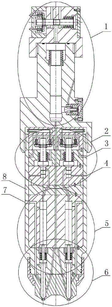
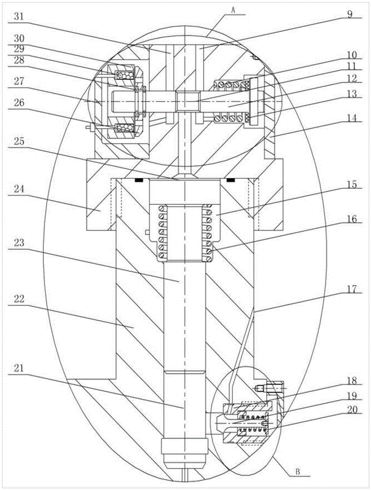
[0024] The combined supercharged double electromagnetic gas injection device of the present invention is mainly composed of a booster part 1 , a double solenoid valve part 2 , a double control piston part 5 , a double needle valve nozzle part 6 and an injection device body 8 . The injection device body 8 has a first low-pressure oil drain port 2, a second low-pressure oil drain port 3, a control oil inlet 7, and the like.

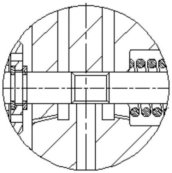
[0025] The pressurized part 1 is located above the injection device body 8, and the two are connected by threads. The booster part 1 mainly includes a solenoid valve A, an intake valve B, a booster piston spring 16, a booster piston sleeve 22, a booster piston 23, a solenoid valve seat 24, and the like. Among them, solenoid valve A is composed of solenoid valve spring 10, solenoid valve stem 12, spring washer 13, baffle plate 14, solenoid valv...


PUM


Abstract

The invention provides a combined type pressurizing double-electromagnetic-valve gas injection device which comprises a pressurizing part, a double-electromagnetic-valve part, a double-control-piston part, a double-needle-valve-nozzle part and an injection device body. The pressurizing part is located on the upper portion of the injection device body. The double-electromagnetic-valve part is located at the position, below the pressurizing part, in the injection device body. The double-control-piston part is located at the position, below the double-electromagnetic-valve part, in the injection device body. The double-needle-valve-nozzle part is located on the lower portion of the injection device body. The combined type pressurizing double-electromagnetic-valve gas injection device can be matched with an engine with a wide power range, and gas leakage and static control oil leakage are avoided. Two electromagnetic valves are adopted for controlling two nozzles to inject gas separately, the two nozzles share one pressurizing piston to achieve gas pressurization, and the gas injection process can be switched between a pressurizing mode and a non-pressurizing mode. The gas injection process and the gas pressurizing process are controlled separately, injection pressure can be adjusted, the injection law is flexible and changeable, and the needs for the power of the engine under different working conditions and the power of serialized engines are met.

Description

technical field [0001] The invention relates to a dual-fuel engine gas injection device, in particular to a combined supercharged dual electromagnetic gas injection device. Background technique [0002] With the continuous consumption of fossil fuels and the increasingly stringent emission regulations of internal combustion engines, the development of engines is facing the dual pressure of energy crisis and environmental pollution. The use of alternative fuels is an effective means to solve both energy problems and environmental pollution. Natural gas and petroleum gas have become the main substitute fuels for internal combustion engines due to their abundant resources, low price, clean combustion, and high calorific value. [0003] The current in-cylinder direct injection gas injection system mainly controls the movement of the needle valve through the internal integrated high-speed solenoid valve to realize the opening and closing of the gas injection valve, which can cont...

Claims


Application Information

Patent Timeline
Patent Type & Authority Applications(China)
IPC IPC(8): F02M21/02
CPCF02M21/0227F02M21/0245F02M21/0254F02M21/0257F02M21/0263Y02T10/30
Inventor 范立云彭怀利宋恩哲董全董晓露刘友
Owner HARBIN ENG UNIV
Why Eureka
Try Eureka